
Datasheet


LTC4020
18
4020fd
For more information www.linear.com/LTC4020
operaTion
Battery Charger Operation
(See Block Diagrams)
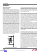
During the majority of a normal battery charge cycle
, the
LTC4020 makes a low impedance connection between
the battery and the DC/DC converter output through the
PowerPath FET, as in Figure 3. This PFET is controlled by
the LTC4020 through modulation of the BGATE pin, which
is connected to the FET gate. When charging is disabled,
the FET is disabled, disconnecting the battery from the
converter output by pulling the gate of the PowerPath FET
high via the BGATE pin. The converter output is regulated
by V
FBMAX
while the FET is disabled. When normal charger
operation resumes, the gate is pulled low. As the BGATE pin
is a slow-moving node, C/10 detection is disabled until the
BGATE pin approaches its normal operating voltage, which
prevents premature C/10 detection during reconnection of
the battery. The slow movement of BGATE can also cause
the converter output to regulate to V
FBMAX
for a short time
during start-up until the FET is enabled. This FET is also
linearly controlled during low battery conditions to enable
the instant-on function, where the converter output can be
separated from a heavily discharged battery to power the
rest of the system before the battery voltage responds to
charging. C/10 detection is also disabled when the charger
is operating in instant-on mode. This FET is also automati
-
cally configured as a 14mV ideal diode, which provides a
low
loss path from the batter
y to the output when system
loads require power from the battery while the battery is
disconnected from the converter output.
The battery charger takes control of the DC/DC converter
operation by modulating the ITH pin voltage in response to
sensed battery charge current, battery voltage, and input
voltage. The converter thus provides exactly the amount
of power required to satisfy both the system load and
battery charger requirements.
Battery charge current is monitored via an external sense
resistor connected to the pins CSP and CSN. The voltage
across this resistor is amplified internally by a factor of
20, which is output onto pin CSOUT. This output voltage
rides on top of a constant 250mV offset. The CSOUT pin
voltage drives an internal transconductance amplifier that
servos the DC/DC converter’s ITH pin voltage in response
to the current requirements of a charging battery. CSOUT
voltage is also used internally as a charge current monitor
to detect <C/10 current thresholds.
Battery voltage is monitored via the VFB pin. This voltage
drives a transconductance amplifier that servos the DC/DC
converter ITH pin voltage in response to voltage developed
on a charging battery. The transition from constant-current
(CC) to constant-voltage (CV) charging modes is also
detected using this transconductance amplifier. The VFB
voltage is used for all battery voltage monitor thresholds,
each being defined as a percentage of the internal 2.5V
reference voltage.
Input voltage regulation is implemented via the V
IN_REG
pin
for use with poorly regulated or high impedance supplies.
This pin drives a transconductance amplifier that reduces
the ITH pin voltage in response to voltage sensed on the
V
IN_REG
pin falling through 2.5V. This transconductance
amplifier remains active even while battery charging is
disabled, so the input regulation feature continues to
operate regardless of the state of a charge cycle.
The LTC4020 contains an internal charge cycle timer that
is used for time based control of a charge cycle. This func
-
tion is enabled by connecting a capacitor to the TIMER
pin. Grounding this pin disables all timer functions. The
timer is used to terminate a successful CC or CC/CV charge
cycle after a programmed end-of-cycle (T
EOC
) time. This
timer is also used to transition a lead-acid charger to float
charging if charge current does not fall adequately dur
-
ing the absorption phase of the charge cycle within the
programmed T
EOC
time.
Figure 3. Battery Charger PowerPath Diagram
R
CS
V
OUT
SYSTEM
BATTERY
CSP
CSN
BGATE
BAT
VFB
V
FBMIN
4020 F03
Downloaded from Arrow.com.Downloaded from Arrow.com.Downloaded from Arrow.com.Downloaded from Arrow.com.Downloaded from Arrow.com.Downloaded from Arrow.com.Downloaded from Arrow.com.Downloaded from Arrow.com.Downloaded from Arrow.com.Downloaded from Arrow.com.Downloaded from Arrow.com.Downloaded from Arrow.com.Downloaded from Arrow.com.Downloaded from Arrow.com.Downloaded from Arrow.com.Downloaded from Arrow.com.Downloaded from Arrow.com.Downloaded from Arrow.com.