
Datasheet


LTC4020
27
4020fd
For more information www.linear.com/LTC4020
During lead-acid charging (MODE = INTV
CC
), the absorption
mode voltage corresponds to 2.5V on the V
FB
pin. Battery
float voltage (maintenance) corresponds to 2.3125V on the
VFB pin, or 92.5% of the absorption voltage. These volt-
ages typically correspond to 14.4V and 13.3V respectively
for a 6-cell (12V) battery.
The values for R
FB1
and R
FB2
are typically the same as
those used for the divider that programs the converter
safety limit (converter output to the V
FBMAX
pin; see
DC/DC Converter section), which yields a DC/DC converter
maximum regulation voltage, or safety limit, that is 10%
higher than the maximum battery charge voltage.
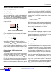
Common Battery Types:
Normalized R
FB1
Resistor Values (R
FB2
= 1)
BATTERY TYPE VOLTAGE R
FB1
1-Cell LiFePO
4
3.6V Float 0.44
1-Cell Li-Ion 4.2V Float 0.68
2-Cell LiFePO
4
7.2V Float 1.88
2-Cell Li-Ion 8.4V Float 2.36
6-Cell Lead-Acid 12V Battery 4.76
3-Cell LiFePO
4
10.8V Float 3.32
3-Cell Li-Ion 12.6V Float 4.04
4-Cell LiFePO
4
14.4V Float 4.76
6-Cell LiFePO
4
21.6V Float 7.64
12-Cell Lead-Acid 24V Battery 10.52
R
CS
: Battery Charge Current Programming
The LTC4020 senses battery charge current using a sense
resistor that is connected between the CSP and CSN
pins. Maximum average battery charge current (I
CSMAX
)
is programmed by setting the value of this current sense
resistor. The resistor value is selected so the desired
maximum charge current through that sense resistor
creates a 50mV drop, or:
R
CS
=
0.05V
I
CSMAX
For example, for a maximum average charge current of
5A, use a 0.01Ω sense resistor.
PowerPath FET Function and Instant-On
The LTC4020 controls an external PMOS with its gate
connected to the BGATE pin. This PowerPath FET controls
current flow to and from the battery.
During a normal battery charge cycle, the BGATE pin is
pulled low (clamped at V
GS
= 9.5V), which operates the FET
as a low impedance connection from the DC/DC converter
output to the battery, effectively shorting the battery to the
converter output. This minimizes power dissipation from
charge current passing thorough the FET. When there is
no V
IN
power or when the IC is in shutdown, LTC4020
connects the battery to the converter output by holding
the BGATE pin low, again effectively shorting the battery
to the converter output. This minimizes power dissipation
while the output is powered by the battery.
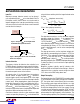
The LTC4020 controls the PowerPath FET to perform
instant-on operation when a charge cycle is initiated
into a heavily discharged battery. If the battery voltage is
below a programmed minimum operational output volt
-
age, corresponding to V
FBMIN
= 2.125V, the PowerPath
FET is configured as a linear regulator, allowing the DC/
DC converter output to rise above the battery voltage
while still providing charge current into the battery.
During instant-on operation, the BGATE pin is driven by the
LTC4020 to maintain the minimum programmed voltage
on the PowerPath FET source, the FET acting as a high
impedance current source, providing charge current to
the battery, independent of the battery voltage.
applicaTions inForMaTion
Figure 12. Instant-On DC/DC Converter Output vs Battery
Voltage Characteristics
V
BAT
(V)
4020 F12
V
OUT
V
FBMIN
= 2.125V
V
BAT
Downloaded from Arrow.com.Downloaded from Arrow.com.Downloaded from Arrow.com.Downloaded from Arrow.com.Downloaded from Arrow.com.Downloaded from Arrow.com.Downloaded from Arrow.com.Downloaded from Arrow.com.Downloaded from Arrow.com.Downloaded from Arrow.com.Downloaded from Arrow.com.Downloaded from Arrow.com.Downloaded from Arrow.com.Downloaded from Arrow.com.Downloaded from Arrow.com.Downloaded from Arrow.com.Downloaded from Arrow.com.Downloaded from Arrow.com.Downloaded from Arrow.com.Downloaded from Arrow.com.Downloaded from Arrow.com.Downloaded from Arrow.com.Downloaded from Arrow.com.Downloaded from Arrow.com.Downloaded from Arrow.com.Downloaded from Arrow.com.Downloaded from Arrow.com.