
Datasheet


LTC4020
30
4020fd
For more information www.linear.com/LTC4020
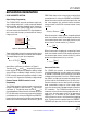
TIMER: C/10 Termination
The LTC4020 supports a low current based termination
scheme. This termination mode is engaged by shorting
the TIMER pin to ground.
When in CC/CV charge mode, a battery charge cycle ter
-
minates when the current output from the charger falls to
below
one-tenth the maximum
charge current, or I
CSMAX
,
as programmed with R
CS
. The C/10 threshold current
corresponds to 5mV across R
CS
.
During lead-acid charging, the LTC4020 initiates float
charging when the absorption stage charge current is re
-
duced to one-tenth of the programmed maximum current.
When charging in CC mode, the current source function
remains active indefinitely.
There is no provision for bad battery detection if C/10
termination is used.
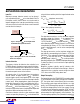
TIMER: Timed Functions
The LTC4020 supports timer based functions, where bat
-
tery charge cycle control occurs after a specific amount
of time elapses.
Timer termination is engaged when a
capacitor (C
TIMER
) is connected from the TIMER pin to
ground. C
TIMER
for a desired end-of-cycle time (T
EOC
)
follows the relation:
C
TIMER
= T
EOC
• 6.87 x 10
–2
(µF)
where T
EOC
is hours.
A typical timer T
EOC
for Li-Ion charge cycle termination
is three hours, which requires a 0.2µF timer capacitor.
The timer cycle starts when the charger transitions from
constant-current to constant-voltage charging, thus, ter
-
mination at the end of the timer cycle only occurs if the
charging cycle was successful.
When timer termination is
used, the STAT1 status pin is pulled low during a charging
cycle until the battery charge current falls below the C/10
threshold. The STAT1 pin stays high impedance with charge
currents below C/10, but the charger continues to top off
the battery until timer T
EOC
, when the LTC4020 terminates
the charging cycle and the PowerPath FET disconnects the
battery from the DC/DC converter output.
During lead-acid charging, the timer acts as an absorp
-
tion mode safety timer. Normally, the LTC4020
initiates
float charging when the absorption stage charge current
is reduced to one-tenth of the programmed maximum
current, however, the maximum duration of absorption
charging is limited by the timer. If the charge current does
not fall to one-tenth of the programmed maximum current
by T
EOC
, the LTC4020 forces the battery charger to begin
float mode charging. A typical timer T
EOC
for lead-acid
charging is six to eight hours, which is accommodated
by a 0.47µF timer capacitor.
When charging in CC mode, after charge termination, once
the timer reaches T
EOC
and the charge cycle terminates,
input power or SHDN must be cycled to initiate another
battery charge cycle.
A bad battery detection function is available during
CC/CV or lead-acid charging. This fault condition is achieved
if the battery does not respond to preconditioning (V
FB
<
1.75V), such that the charger remains in (or enters) pre-
condition mode after one-eighth of the programmed T
EOC
time. A bad battery fault halts the charging cycle, and the
fault condition is reported on the status pins. The bad battery
fault remains active until the battery voltage rises above the
precondition threshold, or until power or SHDN is cycled.
Battery Temperature Qualified Charging: NTC
The LTC4020 can accommodate battery temperature moni
-
toring by using an NTC (negative temperature co-efficient)
thermistor close to the battery pack
. The temperature
monitoring function is enabled by connecting a 10kΩ,
β = 3380 NTC thermistor from the NTC pin to ground. If
the NTC function is not desired, leave the pin unconnected.
The NTC pin sources 50µA, and monitors the voltage
dropped across the 10kΩ thermistor. When the voltage
on this pin is above 1.35V (0°C) or below 0.3V (40°C),
the battery temperature is out of range, and the LTC4020
triggers an NTC fault. The NTC fault condition remains until
the voltage on the NTC pin corresponds to a temperature
within the 0°C to 40°C range. Both hot and cold thresholds
incorporate hysteresis that corresponds to 5°C.
If higher operational charging temperatures are desired,
the temperature range can be expanded by adding series
resistance to the 10k NTC resistor. Adding a 910Ω resistor
will increase the effective HOT temperature threshold to
45°C. The effect of this additional resistance on the COLD
threshold is negligible.
applicaTions inForMaTion
Downloaded from Arrow.com.Downloaded from Arrow.com.Downloaded from Arrow.com.Downloaded from Arrow.com.Downloaded from Arrow.com.Downloaded from Arrow.com.Downloaded from Arrow.com.Downloaded from Arrow.com.Downloaded from Arrow.com.Downloaded from Arrow.com.Downloaded from Arrow.com.Downloaded from Arrow.com.Downloaded from Arrow.com.Downloaded from Arrow.com.Downloaded from Arrow.com.Downloaded from Arrow.com.Downloaded from Arrow.com.Downloaded from Arrow.com.Downloaded from Arrow.com.Downloaded from Arrow.com.Downloaded from Arrow.com.Downloaded from Arrow.com.Downloaded from Arrow.com.Downloaded from Arrow.com.Downloaded from Arrow.com.Downloaded from Arrow.com.Downloaded from Arrow.com.Downloaded from Arrow.com.Downloaded from Arrow.com.Downloaded from Arrow.com.