
Datasheet

LTC4020
4
4020fd
For more information www.linear.com/LTC4020
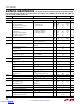
SYMBOL PARAMETER CONDITIONS MIN TYP MAX UNITS
Battery Charger
V
BAT
Charger Output Voltage Range
l
55 V
V
FB
Float Reference
Auto Recharge Voltage
Precondition Threshold (Rising)
Precondition Hysteresis
CC/CV Charging (MODE = 0V)
% of Float Reference
% of Float Reference
l
l
l
2.4875
2.475
96.5
68
2.5
97.5
70
85
2.5125
2.525
98.5
72
V
V
%
%
mV
Absorption Reference
Float Reference
Bulk Charge Threshold (Falling)
Precondition Threshold (Rising)
Precondition Hysteresis
Lead-Acid Charging
(MODE = INT
V
CC
)
% of Absorption Reference
% of Absorption Reference
% of Absorption Reference
l
l
l
l
2.4875
2.475
91.5
86
68
2.5
92.5
87.5
70
85
2.5125
2.525
93.5
89
72
V
V
%
%
%
mV
V
oltage Reference CC Charging (MODE = - NC -)
l
2.4875
2.475
2.5 2.5125
2.525
V
V
V
IN_REG
Input Regulation Reference % of Float (CC/CV), Safety (CC), or
Absorption (LA) Reference
l
98 100 102 %
V
FBMIN
Instant-On Reference % of Float (CC/CV) or Absorption (LA)
Reference
l
84 85 86 %
C/10 Detection Enable (Rising)
Hysteresis (Falling)
2.175
20
V
mV
Instant-On Charge Current Reduction
Threshold
V
CSN
– V
BAT
; Note 4 0.45 V
C/10 Detection Enable
C/10 Detection Hysteresis
V
CSN
– V
BAT
Falling
V
CSN
– V
BAT
Rising
1.05
150
V
mV
Charge Current Reduction Gain ΔV
CS(MAX)
/Δ(V
CSN
– V
BAT
);Note 4 –33 mV/V
I
BATQ
Battery Bias Currents with PowerPath
Switcher Disabled
I
CSP
+ I
CSN
+ I
BAT
l
9 18 µA
CSN, CSP Charger Current Sense Pin Operating Bias
Currents
I
CSP
= I
CSN
; Charging Enabled 40 µA
Charger Current Sense Limit Voltage V
CSP
– V
CSN
l
47.5 50 52.5 mV
Charger Current Sense Termination Voltage
(C/10)
V
CSP
– V
CSN
; MODE = 0V
l
3 5 7 mV
Charger Current Sense Precondition Voltage V
CSP
– V
CSN
; V
FB
= 1.5
l
1.5 3 4.5 mV
Sense Input UVLO
UVLO Hysteresis
V
CSP
Rising (Charging Enabled)
V
CSP
Falling (Charging Disabled)
l
1.6 1.75
100
1.9 V
mV
CSOUT Offset V
CSP
= V
CSN
l
0.225 0.25 0.290 V
Gain ΔV
CSOUT
/ Δ(V
CSP
– V
CSN
)
l
19 20 21 V/V
RNG/SS Current Limit Programming V
RNG/SS
= 0.5V; V
RNG/SS
/V
CS(MAX)
l
18 20 22 V/V
NTC NTC Range Limit (High)
NTC Range Limit (Low)
NTC Range Hysteresis
V
NTC
Rising
V
NTC
Falling
% of V
NTC(H,L)
l
l
1.30
0.27
1.35
0.3
20
1.40
0.33
V
V
%
I
NTC
NTC Pin Bias Current V
NTC
= 0.8V
l
47.5 50 52.5 µA
NTC Disable Current INTC Pin Current (Falling) 3.5 µA
NTC Disable Current Hysteresis 2 µA
V
BGATE
Gate Clamp Voltage V
CSN
– V
BGATE
l
7 9.5 12 V
C/10 Detection Enable (Falling)
C/10 Detection Enable Hysteresis
V
CSN
< 7V 0.425
0.125
V
V
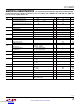
elecTrical characTerisTics
The l denotes the specifications which apply over the specified operating
junction temperature range, otherwise specifications are at T
A
= 25°C (Note 2). PV
IN
= SENSVIN = CSP = CSN = BAT = 20V, SHDN = 2V,
C
(TG1, BG1, TG2, BG2)
= 1000pF, V
RNG/SS
= 2V.
Downloaded from Arrow.com.Downloaded from Arrow.com.Downloaded from Arrow.com.Downloaded from Arrow.com.