
Datasheet

LTC4225-1/LTC4225-2
12
422512f
Board Presence Detect with EN
If ON is high when the EN pin goes low, indicating a board
presence, the LTC4225 initiates a 100ms timing cycle for
contact debounce. Upon board insertion, any bounces
on the EN pin restart the timing cycle. When the 100ms
timing cycle is done, the internal fault latches are cleared.
If the EN pin remains low at the end of the timing cycle,
HGATE is charged up with a 10µA current source to turn
on the Hot Swap MOSFET.
If the EN pin goes high, indicating a board removal, the
HGATE pin is pulled low with a 300µA current sink after
a 20µs delay, turning off the Hot Swap MOSFET without
clearing any latched faults.
Overcurrent Fault
The LTC4225 features an adjustable current limit with circuit
breaker function that protects the external MOSFETs against
short circuits or excessive load current. The voltage across
the external sense resistor (R
S1
, R
S2
) is monitored by an
electronic circuit breaker (ECB) and active current limit
(ACL) amplifier. The electronic circuit breaker will turn off
the Hot Swap MOSFET with a 200mA current from HGATE
to OUT if the voltage across the sense resistor exceeds
∆V
SENSE(CB)
(50mV) for longer than the fault filter delay
configured at the TMR pin.
Active current limiting begins when the sense voltage
exceeds the ACL threshold ∆V
SENSE(ACL)
(65mV), which
is 1.3× the ECB threshold ∆V
SENSE(CB)
. The gate of the
Hot Swap MOSFET is brought under control by the ACL
amplifier and the output current is regulated to maintain
the ACL threshold across the sense resistor. At this point,
the fault filter starts the timeout with a 100µA current
charging the TMR pin capacitor. If the TMR pin voltage
exceeds its threshold (1.235V), the external MOSFET
turns off with HGATE pulled to ground by 300µA, and its
associated FAULT pulls low.
After the Hot Swap MOSFET turns off, the TMR pin ca-
pacitor is discharged with a 2µA pull-down current until
its threshold reaches 0.2V. This is followed by a cool-off
period of 14 timing cycles at the TMR pin. For the latch-off
part (LTC4225-1), the HGATE pin voltage does not restart
at the end of the cool-off period, unless the latched fault
is cleared by pulling the ON pin low or toggling the EN
pin from high to low. For the auto-retry part (LTC4225-2),
the latched fault is cleared automatically at the end of the
cool-off period, and the HGATE pin restarts charging up
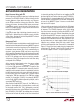
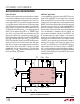
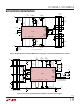
to turn on the MOSFET. Figure 4 shows an overcurrent
fault on the 12V output.
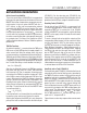
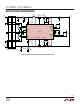
In the event of a severe short-circuit fault on the 12V output
as shown in Figure 5, the output current can surge to tens
of amperes. The LTC4225 responds within 1µs to bring
the current under control by pulling the HGATE to OUT
voltage down to zero volts. Almost immediately, the gate
of the Hot Swap MOSFET recovers rapidly due to the R
HG
and C
HG
network, and current is actively limited until the
electronic circuit breaker times out. Due to parasitic sup-
ply lead inductance, an input supply without any bypass
capacitor may collapse during the high current surge
and then spike upwards when the current is interrupted.
Figure11 shows the input supply transient suppressors
consisting of Z1, R
SNUB1
, C
SNUB1
and Z2, R
SNUB2
, C
SNUB2
for the two supplies if there is no input capacitance.
applicaTions inForMaTion
Figure 4. Overcurrent Fault on 12V Output
Figure 5. Severe Short-Circuit on 12V Output
OUT
10V/DIV
HGATE
10V/DIV
I
LOAD
40A/DIV
100µs/DIV
422512 F04
OUT
10V/DIV
HGATE
10V/DIV
I
LOAD
40A/DIV
2µs/DIV
422512 F05