
Datasheet


LTC4252-1/LTC4252-2
LTC4252A-1/LTC4252A-2
26
425212fe
For more information www.linear.com/LTC4252-1
applicaTions inForMaTion
CB FAULT
TIMER
GATE
SENSE
V
OUT
SS
DRAIN
PWRGD
TIMER
GATE
SENSE
V
OUT
SS
DRAIN
PWRGD
TIMER
GATE
SENSE
V
OUT
SS
DRAIN
PWRGD
CB FAULTCB FAULT CB FAULT
5.8µA
5.8µA
1 2
425212 F14
1 2
CB TIMES OUT
1 432
CB TIMES OUT
V
ACL
V
CB
V
ACL
V
DRNCL
V
CB
V
ACL
V
TMRH
V
TMRH
V
TMRH
V
CB
230µA + 8 • I
DRN
V
DRNCL
230µA + 8 • I
DRN
230µA + 8 • I
DRN
230µA + 8 • I
DRN
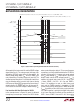
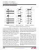
(14a) Momentary Circuit-Breaker Fault
Figure 14. Circuit-Breaker Timing Behavior (All Waveforms Are Referenced to V
EE
)
(14b) Circuit-Breaker Time Out (14c) Multiple Circuit-Breaker Fault
the V
TMRH
threshold, TIMER is discharged by 5.8µA. In
Figure 14b, when TIMER exceeds V
TMRH
, GATE pulls down
immediately and the LTC4252 shuts down. In Figure 14c,
multiple momentary faults cause the TIMER capacitor to
integrate and reach V
TMRH
. GATE pull down follows and
the LTC4252 shuts down. During shutdown, the LTC4252-1
latches TIMER high with a 5.8µA pull-up current source;
the LTC4252-2 activates a shutdown cooling cycle.
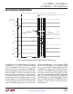
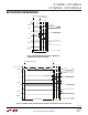
Resetting a Fault Latch (LTC4252-1)
The latched circuit breaker fault of LTC4252-1 benefits
from long cooling time. It is reset by pulling the UV pin
below V
UVLO
with a switch. Reset is also accomplished by
pulling the V
IN
pin momentarily below (V
LKO
– V
LKH
). A
third reset method involves pulling the TIMER pin below
V
TMRL
as shown in Figure 15. An initial timing cycle is
skipped if TIMER is used for reset. An initial timing cycle
is generated if reset by the UV pin or the V
IN
pin.
The duration of the TIMER reset pulse should be smaller
than the time taken to reach 0.2V at SS pin. With a single
pole mechanical pushbutton switch, this may not be
feasible. A double pole, single throw pushbutton switch
removes this restriction by connecting the second switch
to the SS pin. With this method, both the SS and TIMER
pins are released at the same time (see Figure 24).
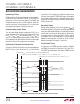
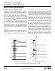
Shutdown Cooling Cycle (LTC4252-2)
Figure 16 shows the timer behavior of the LTC4252-2. At
time point 2, TIMER exceeds V
TMRH
, GATE pulls down
immediately and the LTC4252 shuts down. TIMER starts
a shutdown cooling cycle by discharging TIMER with
5.8µA to the V
TMRL
threshold. TIMER then charges with
5.8µA to the V
TMRH
threshold. There are four 5.8µA
discharge phases and three 5.8µA charge phases in this
shutdown cooling cycle spanning time points 2 and 3. At
time point 3, the LTC4252 automatic retry occurs with a
start-up cycle. Good thermal management techniques are
highly recommended; power and thermal dissipation must
be carefully evaluated when implementing the automatic
retry scheme.