
Datasheet

LTC4260
22
4260fc
For more information www.linear.com/LTC4260
applicaTions inForMaTion
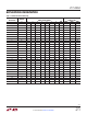
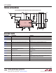
Table 2. LTC4260 Register Addresses and Contents
REGISTER
ADDRESS*
REGISTER
NAME
READ/WRITE DESCRIPTION
00h CONTROL (A) R/W Controls Whether the Part Retries After Faults, Set the Switch State
01h ALERT (B) R/W Controls Whether the ALERT Pin is Pulled Low After a Fault is Logged in the Fault Register
02h STATUS (C) R System Status Information
03h FAULT (D) R/W Fault Log
04h SENSE (E) R/W** ADC Current Sense Voltage Data
05h SOURCE (F) R/W** ADC SOURCE Voltage Data
06h, 07h ADIN (G) R/W** ADC ADIN Voltage Data
*Register address MSBs b7-b3 are ignored.
**Writable if bit A5 set.
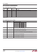
Table 3. CONTROL Register A (00h)—Read/Write
BIT NAME OPERATION
A7:6 GPIO Configure Configures Behavior of GPIO Pin
FUNCTION A6 A7 GPIO PIN
Power Good (Default) 0 0 GPIO = C3
Power Bad 0 1 GPIO = C3
General Purpose Output 1 0 GPIO = B6
General Purpose Input 1 1 GPIO = Hi-Z
A5 Test Mode Enable Test Mode Halts ADC Operation and Enables Writes to ADC Registers
1 = Enable Test Mode, 0 = Disable Test Mode (Default)
A4 Mass Write Enable Enables Mass Write Using Address (1011 111)b
1 = Enable Mass Write (Default), 0 = Disable Mass Write
A3 FET On Control Turns FET On and Off
1 = Turn FET On, 0 = Turn FET Off. Defaults to ON Pin State at End of Debounce Delay
A2 Overcurrent Autoretry Enables Autoretry After an Overcurrent Fault
1 = Retry Enabled, 0 = Retry Disabled (Default)
A1 Undervoltage Autoretry Enables Autoretry After an Undervoltage Fault
1 = Retry Enabled (Default), 0 = Retry Disabled
A0 Overvoltage Autoretry Enables Autoretry After an Overvoltage Fault
1 = Retry Enabled (Default), 0 = Retry Disabled