
Datasheet

LTC4266
17
4266fe
For more information www.linear.com/LTC4266
RESISTANCE
PD
PSE
0Ω 10k
15k
4266 F11
19k 26.5k
26.25k23.75k
150Ω (NIC)
20k 30k
33k
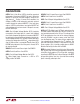
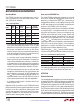
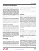
Figure 11. IEEE 802.3af Signature Resistance Ranges
ApplicAtions inForMAtion
the must-accept and must-reject ranges. In particular, the
PSE must reject standard computer network ports, many
of which have 150Ω common mode termination resistors
that will be damaged if power is applied to them (the black
region at the left of Figure 11).
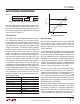
4-Point Detection
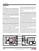
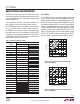
The LTC4266 uses a 4-point detection method to discover
PDs. False-positive detections are minimized by check-
ing for signature resistance with both forced-current and
forced-voltage measurements. Initially, two test currents
are forced onto the port (via the OUTn pin) and the resulting
voltages are measured. The detection circuitry subtracts
the two V-I points to determine the resistive slope while
removing offset caused by series diodes or leakage at
the port (see Figure 12). If the forced-current detection
yields a valid signature resistance, two test voltages are
then forced onto the port and the resulting currents are
measured and subtracted. Both methods must report
valid resistances for the port to report a valid detection.
PD signature resistances between 17k and 29k (typically)
are detected as valid and reported as Detect Good in the
corresponding Port Status register. Values outside this
range, including open and short circuits, are also reported.
If the port measures less than 1V at the first forced-current
test, the detection cycle will abort and Short Circuit will
be reported. Table 3 shows the possible detection results.
Table 3. Detection Status
MEASURED PD SIGNATURE DETECTION RESULT
Incomplete or Not Yet Tested Detect Status Unknown
<2.4k Short Circuit
Capacitance > 2.7µF C
PD
too High
2.4k < R
PD
< 17k R
SIG
too Low
17k < R
PD
< 29k Detect Good
>29k R
SIG
too High
>50k Open Circuit
Voltage > 10V Port Voltage Outside Detect Range
Operating Modes
The port’s operating mode determines when the LTC4266
runs a detection cycle. In manual mode, the port will
idle until the host orders a detect cycle. It will then run
detection, report the results, and return to idle to wait for
another command.
In semi-auto mode, the LTC4266 autonomously polls a port
for PDs, but it will not apply power until commanded to do
so by the host. The Port Status register is updated at the
end of each detection cycle. If a valid signature resistance
is detected and classification is enabled, the port will clas-
sify the PD and report that result as well. The port will then
wait for at least 100ms (or 2 seconds if midspan mode is
enabled), and will repeat the detection cycle to ensure that
the data in the port status register is up-to-date.
If the port is in semi-auto mode and high power opera-
tion is enabled, the port will not turn on in response to
a power-on command unless the current detect result is
Detect Good. Any other detect result will generate a t
START
fault if a power-on command is received. If the port is not
in high power mode, it will ignore the detection result and
apply power when commanded, maintaining backwards
compatibility with the LTC4259A.
Behavior in AUTO pin mode is similar to semi-auto; however,
after Detect Good is reported and the port is classified (if
classification is enabled), it is automatically powered on
without further intervention. In AUTO pin mode, the I
CUT
and I
LIM
thresholds are automatically set; see the Reset
and the AUTO/MID Pins section for more information.
Figure 12. PD Detection
FIRST
DETECTION
POINT
SECOND
DETECTION
POINT
VALID PD
25kΩ SLOPE
275
165
CURRENT (µA)
0V-2V
OFFSET
VOLTAGE
4266 F12