
Datasheet

LTC4266
19
4266fe
For more information www.linear.com/LTC4266
ApplicAtions inForMAtion
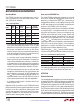
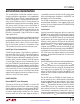
The second 802.3at classification method, known as
2-event classification or ping-pong, is fully supported by
the LTC4266. A Type 2 PD that is requesting more than
13W will indicate Class 4 during normal 802.3af classifi-
cation. If the LTC4266 sees Class 4, it forces the port to a
specified lower voltage (called the mark voltage, typically
9V), pauses briefly, and then re-runs classification to
verify the Class 4 reading (Figure 1). It also sets a bit in
the High Power Status register to indicate that it ran the
second classification cycle. The second cycle alerts the
PD that it is connected to a Type 2 PSE which can supply
Type 2 power levels.
2-event ping-pong classification is enabled by setting a bit
in the port’s High Power Mode register. Note that a ping-
pong enabled port only runs the second classification cycle
when it detects a Class 4 device; if the first cycle returns
Class 0 to 3, the port assumes it is connected to a Type
1 PD and does not run the second classification cycle.
Invalid Type 2 Class Combinations
The 802.3at spec defines a Type 2 PD class signature as
two consecutive Class 4 results; a Class 4 followed by a
Class 0-3 is not a valid signature. In AUTO pin mode, the
LTC4266 will power a detected PD regardless of the clas-
sification results, with one exception: if the PD presents
an invalid Type 2 signature (Class 4 followed by Class 0
to 3), the LTC4266 will not provide power and will restart
the detection process. To aid in diagnosis, the Port Status
register will always report the results of the last class pulse,
so an invalid Class 4–Class 2 combination would report
a second class pulse was run in the High Power Status
register (which implies that the first cycle found Class 4),
and Class 2 in the Port Status register.
POWER CONTROL
External MOSFET, Sense R Summary
The primary function of the LTC4266 is to control the
delivery of power to the PSE port. It does this by control-
ling the gate drive voltage of an external power MOSFET
while monitoring the current via an external sense resis-
tor and the output voltage at the OUT pin. This circuitry
serves to couple the raw V
EE
input supply to the port in
a controlled manner that satisfies the PD’s power needs
while minimizing power dissipation in the MOSFET and
disturbances on the V
EE
backplane.
The LTC4266 is designed to use 0.25Ω sense resistors to
minimize power dissipation. It also supports 0.5Ω sense
resistors, which are the default when LTC4258/LTC4259A
compatibility is desired.
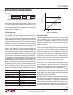
Inrush Control
Once the command has been given to turn on a port, the
LTC4266 ramps up the GATE pin of that port’s external
MOSFET in a controlled manner. Under normal power-up
circumstances, the MOSFET gate will rise until the port
current reaches the inrush current limit level (typically
450mA), at which point the GATE pin will be servoed to
maintain the specified I
INRUSH
current. During this inrush
period, a timer (t
START
) runs. When output charging is
complete, the port current will fall and the GATE pin will
be allowed to continue rising to fully enhance the MOSFET
and minimize its on-resistance. The final V
GS
is nominally
12V. If the t
START
timer expires before the inrush period
completes, the port will be turned back off and a t
START
fault reported.
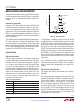
Current Limit
Each LTC4266 port includes two current limiting thresholds
(I
CUT
and I
LIM
), each with a corresponding timer (t
CUT
and t
LIM
). Setting the I
CUT
and I
LIM
thresholds depends
on several factors: the class of the PD, the voltage of the
main supply (V
EE
), the type of PSE (1 or 2), the sense
resistor (0.5Ω or 0.25Ω), the SOA of the MOSFET, and
whether or not the system is required to implement class
enforcement.
Per the IEEE spec, the LTC4266 will allow the port cur-
rent to exceed I
CUT
for a limited period of time before
removing power from the port, whereas it will actively
control the MOSFET gate drive to keep the port current
below I
LIM
. The port does not take any action to limit the
current when only the I
CUT
threshold is exceeded, but
does start the t
CUT
timer. The t
LIM
timer starts when the
I
LIM
threshold is exceeded and current limit is active. If
the current drops below the I
CUT
current threshold before
its timer expires, the t
CUT
timer counts back down, but