
Datasheet

LTC4266
21
4266fe
For more information www.linear.com/LTC4266
ApplicAtions inForMAtion
The LTC4266 will support current levels well beyond the
maximum values in the 802.3at specification. The shaded
areas in Table 5 indicate settings that may require a larger
external MOSFET, additional heat sinking, or a reduced
t
LIM
setting.
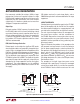
MOSFET Fault Detection
LTC4266 PSE ports are designed to tolerate significant
levels of abuse, but in extreme cases it is possible for
the external MOSFET to be damaged. A failed MOSFET
may short source to drain, which will make the port ap-
pear to be on when it should be off; this condition may
also cause the sense resistor to fuse open, turning off
the port but causing the LTC4266 SENSE pin to rise to
an abnormally high voltage. A failed MOSFET may also
short from gate to drain, causing the LTC4266 GATE pin
to rise to an abnormally high voltage. The LTC4266 SENSE
and GATE pins are designed to tolerate up to 80V faults
without damage.
If the LTC4266 sees any of these conditions for more than
180μs, it disables all port functionality, reduces the gate
drive pull-down current for the port and reports a FET Bad
fault. This is typically a permanent fault, but the host can
attempt to recover by resetting the port, or by resetting
the entire chip if a port reset fails to clear the fault. If the
MOSFET is in fact bad, the fault will quickly return, and
the port will disable itself again. The remaining ports of
the LTC4266 are unaffected.
An open or missing MOSFET will not trigger a FET Bad
fault, but will cause a t
START
fault if the LTC4266 attempts
to turn on the port.
Voltage and Current Readback
The LTC4266 measures the output voltage and current
at each port with an internal A/D converter. Port data is
only valid when the port power is on. The converter has
two modes:
• Slowmode:14samplespersecond,14.5bitsresolution
• Fastmode:440samplespersecond,9.5bitsresolution
In fast mode, the least significant 5 bits of the lower byte are
zeroes so that bit scaling is the same in both modes.
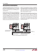
Disconnect
The LTC4266 monitors the port to make sure that the PD
continues to draw the minimum specified current. A dis-
connect timer counts up whenever port current is below
7.5mA (typ), indicating that the PD has been disconnected.
If the t
DIS
timer expires, the port will be turned off and
the disconnect bit in the fault event register will be set.
If the current returns before the t
DIS
timer runs out, the
timer resets and will start counting from the beginning
if the undercurrent condition returns. As long as the PD
exceeds the minimum current level more often than t
DIS
,
it will stay powered.
Although not recommended, the DC disconnect feature can
be disabled by clearing the corresponding DC Disconnect
Enable bits. Note that this defeats the protection mecha-
nisms built into the IEEE spec, since a powered port will
stay powered after the PD is removed. If the still-powered
port is subsequently connected to a non-PoE data device,
the device may be damaged.
The LTC4266 does not include AC disconnect circuitry, but
includes AC disconnect enable bits to maintain compat-
ibility with the LTC4259A. If the AC Disconnect Enable bits
are set, DC disconnect will be used.
Shutdown Pins
The LTC4266 includes a hardware SHDN pin for each port.
When a SHDN pin is pulled to DGND, the corresponding
port will be shut off immediately. The port remains shut
down until re-enabled via I
2
C or a device reset in AUTO
pin mode.
Masked Shutdown
The LTC4266 provides a low latency port shedding fea-
ture to quickly reduce the system load when required. By
allowing a pre-determined set of ports to be turned off,
the current on an overloaded main power supply can be
reduced rapidly while keeping high priority devices pow-
ered. Each port can be configured to high or low priority;
all low-priority ports will shut down within 6.5μs after
the MSD pin is pulled low. If multiple ports in a LTC4266
device are shut down via MSD, they are staggered by at
least 0.55μs to help reduce voltage transients on the main