
Datasheet


LTC4270/LTC4271
19
42701fc
APPLICATIONS INFORMATION
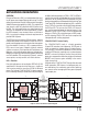
FIRST
DETECTION
POINT
SECOND
DETECTION
POINT
VALID PD
25kΩ SLOPE
275
165
CURRENT (µA)
0V-2V
OFFSET
VOLTAGE
42701 F12
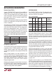
Figure 12. PD Detection
Table 4. Detection Status
MEASURED PD SIGNATURE DETECTION RESULT
Incomplete or Not Yet Tested Detect Status Unknown
< 2.4k Short Circuit
Capacitance > 2.7µF C
PD
too High
2.4k < R
PD
< 17k R
SIG
too Low
17k < R
PD
< 29k Detect Good
> 29k R
SIG
too High
> 50k Open Circuit
Voltage > 10V Port Voltage Outside Detect Range
More on Operating Modes
The port’s operating mode determines when the LTC4270/
LTC4271 runs a detection cycle. In manual mode, the
port
will idle until the host orders a detect cycle. It will then
run detection, report the results, and return to idle to wait
for another command.
In semi-auto mode, the LTC4270/LTC4271 autonomously
polls a port for PDs, but it will not apply power until com-
manded to do so by the host. The Port Status register is
updated at the end of each
detection cycle.
If a valid signature resistance is detected and classification
is enabled, the port will classify the PD and report that
result as well. The port will then wait for at least 100ms (or
2 seconds if midspan mode is enabled), and will repeat the
detection cycle to ensure that the data in the Port Status
register is up-to-date.
If the port is in semi
-auto mode and high power opera-
tion is enabled, the port will not turn on in response to
a power-on command unless the current detect result is
detect good. Any other detect result will generate a t
START
fault if a power-on command is received. In high power
mode the port must be placed in manual mode to force a
port on regardless of detect
outcome.
Behavior in AUTO pin mode is similar to semi-auto; how-
ever, after detect good is reported and the port is classified
(if classification is enabled), it is automatically powered
on without further intervention. In standalone (AUTO pin)
mode, the I
CUT
and I
LIM
thresholds are automatically set;
see the Reset and the AUTO/MID Pins section for more
information.
The signature detection circuitry is disabled
when the
port is initially powered up with the AUTO pin low, in
shutdown mode, or when the corresponding Detect En-
able bit is cleared.
Detection of Legacy PDs
Proprietary PDs that predate the original IEEE 802.3af stan-
dard are commonly referred to today as legacy devices. One
type of legacy PD uses a large common mode capacitance
(>10μF) as the detection signature. Note that PDs in
this
range of capacitance are defined as invalid, so a PSE that
detects legacy PDs is technically noncompliant with the
IEEE spec. The LTC4270/LTC4271 can be configured to
detect this type of legacy PD. Legacy detection is disabled
by default, but can be manually enabled on a per-port basis.
When enabled, the port will report Detect Good when it
sees either a valid IEEE
PD or a high-capacitance legacy
PD. With legacy mode disabled, only valid IEEE PDs will
be recognized.
CLASSIFICATION
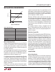
802.3af Classification
A PD may optionally present a classification signature to
the PSE to indicate the maximum power it will draw while
operating. The IEEE specification defines this signature
as a constant current draw when the PSE port voltage is
in the V
CLASS
range (between 15.5V and 20.5V), with the
current level indicating one of 5 possible PD classes. Figure
13 shows a typical PD load line, starting with the slope of
the 25k signature resistor below 10V, then transitioning to