
Datasheet


LTC4274
14
4274fd
OPERATION
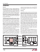
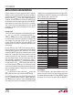
Figure 10. Power Over Ethernet System Diagram
Overview
Power over Ethernet, or PoE, is a standard protocol for
sending DC power over copper Ethernet data wiring.
The IEEE group that administers the 802.3 Ethernet data
standards added PoE powering capability in 2003. This
original PoE spec, known as 802.3af, allowed for 48V DC
power at up to 13W. This initial spec was widely popular,
but 13W was not adequate for some requirements. In
2009, the IEEE released a new standard, known as 802.3at
or PoE+, increasing the voltage and current requirements
to provide 25W of power.
The IEEE standard also defines PoE terminology. A device
that provides power to the network is known as a PSE, or
power sourcing equipment, while a device that draws power
from the network is known as a PD, or powered device.
PSEs come in two types: Endpoints (typically network
switches or routers), which provide data and power; and
Midspans, which provide power but pass through data.
Midspans are typically used to add PoE capability to existing
non-PoE networks. PDs are typically IP phones, wireless
access points, security cameras, and similar devices, but
could be nearly anything that runs from 25W or less and
includes an RJ45-style network connector.
The LTC4274 is a third-generation single PSE controller
in either an endpoint or midspan design. Virtually all nec-
essary circuitry is included to implement a IEEE 802.3at
compliant PSE design, requiring only an external power
MOSFET and sense resistor; these minimize power loss
compared to alternative designs with on-board MOSFETs
and increase system reliability in the event a single chan-
nel is damaged.
PoE Basics
Common Ethernet data connections consist of two or four
twisted pairs of copper wire (commonly known as CAT-5
cable), transformer-coupled at each end to avoid ground
loops. PoE systems take advantage of this coupling ar-
rangement by applying voltage between the center-taps
of the data transformers to transmit power from the PSE
to the PD without affecting data transmission. Figure 10
shows a high-level PoE system schematic.
To avoid damaging legacy data equipment that does not
expect to see DC voltage, the PoE spec defines a protocol
that determines when the PSE may apply and remove
power. Valid PDs are required to have a specific 25k
common-mode resistance at their input. When such a PD
is connected to the cable, the PSE detects this signature
resistance and turns on the power. When the PD is later
disconnected, the PSE senses the open circuit and turns
power off. The PSE also turns off power in the event of a
current fault or short circuit.
When a PD is detected, the PSE optionally looks for a
classification signature that tells the PSE the maximum
power the PD will draw. The PSE can use this information
to allocate power among several ports, police the current
consumption of the PD, or to reject a PD that will draw more
4274 F10
S1B
S1B
SMAJ58A
58V
0.22µF
100V
X7R
1µF
100V
X7R
Tx
Rx
Rx
Tx
SMAJ58A
58V
DATA PAIR
DATA PAIR
V
EE
SENSE GATE OUT
V
DD
INT
SCL
SDAIN
SDAOUT
0.25
IRFM120A
SPARE PAIR
SPARE PAIR
LTC4274
DGND AGND
I
2
C
3.3V
INTERRUPT
–54V
CA
T 5
RJ45
4
5
4
5
1
2
1
2
3
6
3
6
7
8
7
8
RJ45
1N4002
s4
1N4002
s4
PSE PD
R
CLASS
V
IN
PWRGD
V
OUT
LTC4265
GND
DC/DC
CONVERTER
5µF ≤ C
IN
≤ 300µF
+
–
V
OUT
GND
0.1µF
100V