
Datasheet


LTC4300-1/LTC4300-2
11
430012fb
For more information www.linear.com/LTC4300-1
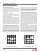
associated with hot swapping have settled. Owing to
their small capacitance, the SDAIN and SCLIN pins cause
minimal disturbance on the backplane busses when they
make contact with the connector.
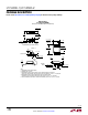
Figure 6 shows the LTC4300-2 in a CompactPCI con-
figuration. The
LTC4300-2 receives its V
CC
voltage from
one of the long “early power” pins. Because this power
is not switched, add a 5Ω to 10Ω resistor between the
V
CC
pins of the connector and the LTC4300-2, as shown
in the figure. In addition, make sure that the V
CC
bypass-
ing on
the backplane is large compared to the 0.01µF
bypass capacitor on the card. Establishing early power
V
CC
ensures that the 1V precharge voltage is present at
the SDAIN and SCLIN pins before they make contact.
Connect V
CC2
to the output of one of the CompactPCI
power supply Hot Swap circuits. V
CC2
is monitored by
a filtered UVLO circuit. With the V
CC2
voltage powering
up after all other pins have established connection, the
UVLO circuit ensures that the backplane and card data
and clock busses are not connected until the transients
associated with hot swapping have settled.
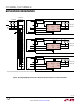
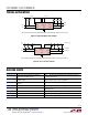
Figure 7 shows the LTC4300-1 in a PCI application,
where
all
of the pins have the same length. In this case, connect
an RC series circuit on the I/O card between V
CC
and
ENABLE. An
RC product of 10ms provides a filter to prevent
the LTC4300-1 from becoming activated until the transients
associated with hot swapping have settled.
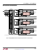
Figure 8 shows the LTC4300-2 in an application where the
user has a custom connector with pins of three different
lengths available. Making V
CC2
the shortest pin ensures
that all other pins are firmly connected before V
CC2
receives any
voltage. A filtered UVLO circuit on V
CC2
ensures that the V
CC2
pin is firmly connected before the
LTC4300-2 connects the backplane to the card.
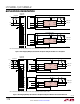
Repeater/Bus Extender Application
Users who wish to connect two 2-wire systems separated
by a distance can do so by connecting two LTC4300-1s
back-to-back, as shown in Figure 9. The I
2
C specification
allows for 400pF maximum bus capacitance, severely
limiting the length of the bus. The SMBus specification
places no restriction on bus capacitance, but the limited
impedances of devices connected to the bus require sys-
tems to
remain small if rise and fall time specifications
are to be met
. The strong pull-up and pull-down imped-
ances of
the LTC4300-1 are capable of meeting rise and
fall time specifications for one nanofarad of capacitance,
thus allowing much more interconnect distance. In this
situation, the differential ground voltage between the two
systems may limit the allowed distance, because a valid
logic LOW voltage with respect to the ground at one end
of the system may violate the allowed V
OL
specification
with respect to the ground at the other end. In addition,
the connection circuitry offset voltages of the back-to-
back LTC4300-1s add together, directly contributing to
the same problem.
Systems with Disparate Supply Voltages (LTC4300-1)
In large 2-wire systems, the V
CC
voltages seen by devices
at various points in the system can differ by a few hun-
dred millivolts
or more. This situation is well modelled by
a series resistor in the V
CC
line, as shown in Figure 10.
For proper operation of the LTC4300-1, make sure that
V
CC(BUS)
≥ V
CC(LTC4300)
– 0.5V.
5V to 3.3V Level Translator and Power Supply
Redundancy (LTC4300-2)
Systems requiring different supply voltages for the back
-
plane side
and the card side can use the LTC4300-2, as
shown in Figure 11. The pull-up resistors on the card side
connect from SDAOUT to SCLOUT to V
CC2
, and those on
the backplane side connect from SDAIN and SCLIN to V
CC
.
The LTC4300-2 functions for voltages ranging from 2.7V
to 5.5V on both V
CC
and V
CC2
. There is no constraint on
the voltage magnitudes of V
CC
and V
CC2
with respect to
each other.
This application also provides power supply redundancy.
If either the V
CC
or V
CC2
voltage falls below its UVLO
threshold, the LTC4300-2 disconnects the backplane
from the card, so that the side that is still powered can
continue to function.
applicaTions inFormaTion