
Datasheet

LTC4300A-1/LTC4300A-2
10
4300a12fa
APPLICATIONS INFORMATION
Resistor Pull-Up Value Selection
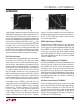
The system pull-up resistors must be strong enough to
provide a positive slew rate of 1.25V/μs on the SDA and
SCL pins, in order to activate the boost pull-up currents
during rising edges. Choose maximum resistor value R
using the formula:
R ≤ (V
CC(MIN)
– 0.6) (800,000) / C
where R is the pull-up resistor value in ohms, V
CC(MIN)
is the minimum V
CC
voltage and C is the equivalent bus
capacitance in picofarads (pF).
In addition, regardless of the bus capacitance, always
choose R ≤ 16k for V
CC
= 5.5V maximum, R ≤ 24k for
V
CC
= 3.6V maximum. The start-up circuitry requires
logic high voltages on SDAOUT and SCLOUT to connect
the backplane to the card, and these pull-up values are
needed to overcome the precharge voltage.
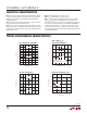
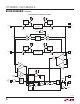
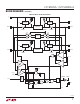
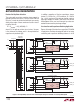
Live Insertion and Capacitance Buffering Application
Figures 3 through 6 illustrate the usage of the LTC4300A
in applications that take advantage of both its hot swap
controlling and capacitance buffering features. In all of
Figure 3. Inserting Multiple I/O Cards into a Live Backplane Using the LTC4300A-1 in a CompactPCI System
STAGGERED CONNECTOR
R13
10k
R12
10k
R14
10k
I/O PERIPHERAL CARD N
ENABLE
SDAIN
SCLIN
U3
LTC4300A-1
V
CC
GND
CARDN_SCL
CARDN_SDA
SDAOUT
SCLOUT
READY
ENABLE
SDAIN
SCLIN
V
CC
GND
SDAOUT
SCLOUT
READY
ENABLE
CARD
ENABLE/DISABLE
SDAIN
SCLIN
V
CC
GND
SDAOUT
SCLOUT
READY
4300a12 F03
ttt
R9
10k
R8
10k
R10
10k
I/O PERIPHERAL CARD 2
U2
LTC4300A-1
CARD2_SCL
CARD2_SDA
STAGGERED CONNECTORSTAGGERED CONNECTOR
R5
10k
R4
10k
R6
10k
I/O PERIPHERAL CARD 1
U1
LTC4300A-1
CARD_SCL
CARD_SDA
R1
10k
V
CC
R2
10k
BACKPLANE
BACKPLANE
CONNECTOR
SDA
BD_SEL
SCL
C1
0.01μF
R3
10k
R7
10k
R11
10k
C3
0.01μF
C5
0.01μF
POWER SUPPLY
HOT SWAP
POWER SUPPLY
HOT SWAP
POWER SUPPLY
HOT SWAP
CARD
ENABLE/DISABLE
CARD
ENABLE/DISABLE