
Datasheet

6
LTC4301L
4301lfa
OPERATIO
U
Start-Up
When the LTC4301L first receives power on its V
CC
pin,
either during power-up or live insertion, it starts in an
undervoltage lockout (UVLO) state, ignoring any activity
on the SDA or SCL pins until V
CC
rises above 2.5V. This is
to ensure that the part does not try to function until it has
enough voltage to do so.
During this time, the 1V precharge circuitry is active and
forces 1V through 200k nominal resistors to the SDAOUT
and SCLOUT pins. Precharging the SCLOUT and SDAOUT
pins to 1V minimizes the worst-case voltage differential
these pins will see at the moment of connection, therefore
minimizing bus disturbances.
Once the LTC4301L comes out of UVLO, it assumes that
SDAIN and SCLIN have been inserted into a live system
and that SDAOUT and SCLOUT are being powered up at
the same time as itself. Therefore, it looks for either a stop
bit or bus idle condition on the backplane side to indicate
the completion of a data transaction. When either one
occurs, the part also verifies that both the SDAOUT and
SCLOUT voltages are high. When all of these conditions
are met, the input-to-output connection circuitry is acti-
vated, joining the SDA and SCL busses on the I/O card with
those on the backplane.
Connection Circuitry
Once the connection circuitry is activated, the functional-
ity of the SDAIN and SDAOUT pins is identical. A low
forced on either pin at any time results in both pin voltages
being low. For proper operation, logic low input voltages
should be no higher than 0.4V with respect to the ground
pin voltage of the LTC4301L. SDAIN and SDAOUT enter a
logic high state only when all devices on both SDAIN and
SDAOUT release high. The same is true for SCLIN and
SCLOUT. This important feature ensures that clock stretch-
ing, clock synchronization, arbitration and the acknowl-
edge protocol always work, regardless of how the devices
in the system are tied to the LTC4301L.
Another key feature of the connection circuitry is that it
provides bidirectional buffering, keeping the backplane
and card capacitances isolated. Because of this isolation,
the waveforms on the backplane busses look slightly
different than the corresponding card bus waveforms as
described here.
Input-to-Output Offset Voltage
When a logic low voltage, V
LOW1
, is driven on any of the
LTC4301L’s data or clock pins, the LTC4301L regulates
the voltage on the other side of the device (call it V
LOW2
)
at a slightly higher voltage, as directed by the following
equation:
V
LOW2
= V
LOW1
+ 75mV + (V
CC
/R) • 70Ω (typical)
where R is the bus pull-up resistance in ohms. For ex-
ample, if a device is forcing SDAOUT to 10mV where V
CC
= 3.3V and the pull-up resistor R on SDAIN is 10k, then the
voltage on SDAIN = 10mV + 75mV + (3.3/10000) • 70 =
108mV(typical). See the Typical Performance Character-
istics section for curves showing the offset voltage as a
function of V
CC
and R.
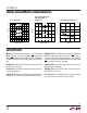
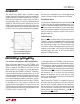
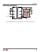
Propagation Delays
During a rising edge, the rise time on each side is deter-
mined by the bus pull-up resistor and the equivalent
capacitance on the line. In Figure 1, V
CC
= 3.3V, SDAOUT
and SCLOUT are pulled-up to 3.3V with 10k resistor (20pF
on this side) and SDAIN and SCLIN are pulled-up to 1.2V
with a 2k resistor (55pF on this side). Lower pull-up
resistor values are used on the input side to allow the
output side to be released sooner.
Figure 1. Input-Output Connection
There is a finite high to low propagation delay through the
connection circuitry for falling waveforms. Figure 2 shows
the falling edge waveforms for the same pull-up resistors
and equivalent capacitance conditions as used in Figure 1.
An external N-channel MOSFET device pulls down the
voltage on the side with 55pF capacitance; LTC4301L pulls
down the voltage on the opposite side with a delay of 60ns.
OUTPUT
SIDE
20pF
INPUT
SIDE
55pF
4301 TA01b
1µs/DIV
0.5V/DIV