
Datasheet

LTC4305
4305f
16
APPLICATIO S I FOR ATIO
WUU
U
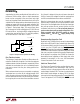
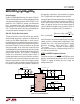
Level Shifting Considerations
In Figure 5, the LTC4305 V
CC
voltage is less than or equal
to both of the downstream bus pull-up voltages, so both
downstream buses can be active at the same time. Like-
wise, the rise time accelerators can be turned on for the
downstream buses, but must never be activated on SCLIN
and SDAIN, because doing so would result in significant
current flow from V
CC
to V
BACK
during rising edges.
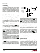
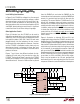
Other Application Circuits
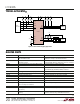
Figure 6 illustrates how the LTC4305 can be used to
expand the number of devices in a system by using nested
addressing. Each I/O card contains a temperature sensor
having device address 1001 000. If both I/O cards were
plugged directly into the backplane, the two sensors
would require two unique addresses. However, if masters
use the LTC4305 in multiplexer mode, where only one
downstream channel is connected at a time, then each
I/O card can have a device with address 1001 000 and no
problems will occur.
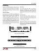
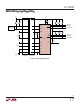
Figures 7 and 8 show two different methods for hot-
swapping I/O cards onto a live two-wire bus using the
LTC4305. The circuitry of Figure 7 consists of an LTC4305
residing on the edge of an I/O card having two separate
downstream buses. Connect a 200k resistor to ground
from the ENABLE pin and make the ENABLE pin the
shortest pin on the card connector, so that the ENABLE pin
remains at a constant logic low while all other pins are
connecting. This ensures that the LTC4305 remains in its
default high impedance state and ignores connection
transients on its SDAIN and SCLIN pins until they have
established solid contact with the backplane 2-wire bus.
In addition, make sure that the ALERT card connector pin
is shorter than the V
CC
pin, so that V
CC
establishes solid
contact with the I/O card pull-up supply pin and powers
the pull-up resistors on ALERT1–ALERT2 before ALERT
makes contact.
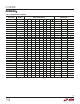
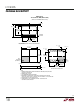
Figure 8 illustrates an alternate SDA and SCL hot-
swapping technique, where the LTC4305 is located on the
backplane and an I/O card plugs into downstream channel
2. Before plugging and unplugging the I/O card, make sure
that channel 2’s downstream switch is open, so that it does
not disturb any 2-wire transaction that may be occurring
at the moment of connection/disconnection. Note that
pull-up resistor R10 on ALERT2 should be located on the
backplane and not the I/O card to ensure proper operation
of the LTC4305 when the I/O card is not present. The pull-
up resistors on SCL2 and SDA2—R8 and R9, respec-
tively—may be located on the I/O card, provided that
downstream bus 2 is never activated when the I/O card is
not present. Otherwise, locate R8 and R9 on the backplane.
Figure 6. Nested Addressing Application
V
CC
V
CC
R5
10k
C1
0.01µF
R6
10k
R7
10k
R3
10k
R4
10k
R1
10k
R2
10k
R8
10k
R9
10k
R10
10k
4305 F06
ADDRESS = 1001 000
I/O CARD #1
ADDRESS = 1001 000
I/O CARD #2
5
3
6
11
10
9
OPEN
8
4
12
13
14
16
15
1
2
7
TEMPERATURE
SENSOR
TEMPERATURE
SENSOR
MICRO-
CONTROLLER
SCLIN
SDAIN
ENABLE
ALERT
READY
ADR2
ALERT1
ADR1
ADR0
GND
SCL1
SDA1
SCL2
SDA2
ALERT2
V
CC
ADDRESS = 1010 000
LTC4305