
Datasheet

LTC4305
4305f
8
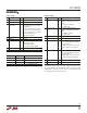
Control Register Bit Definitions
Register 0 (00h)
BIT NAME TYPE* DESCRIPTION
d7 Downstream R Indicates if upstream bus is connected
Connected to any downstream buses
0 = upstream bus disconnected from
all downstream buses
1 = upstream bus connected to one or
more downstream buses
d6 ALERT1 Logic State R Logic state of ALERT1 pin, noninverting
d5 ALERT2 Logic State R Logic state of ALERT2 pin, noninverting
d4 Reserved R Not Used
d3 Reserved R Not Used
d2 Failed Connection R Indicates if an attempt to connect to a
Attempt downstream bus failed because the
“Connection Requirement” bit in
Register 2 was low and the
downstream bus was low
0 = Failed connection attempt occurred
1 = No failed attempts at connection
occurred
d1 Latched Timeout R Latched bit indicating if a timeout has
occurred and has not yet been cleared.
0 = no latched timeout
1 = latched timeout
d0 Timeout Real Time R Indicates real-time status of Stuck Low
Timeout Circuitry
0 = no timeout is occurring
1 = timeout is occurring
Note: Masters write to Register 0 to reset the fault circuitry after a fault
has occurred and been resolved. Because Register 0 is Read-Only, no
other functionality is affected.
* For Type, “R/W” = Read Write, “R” = Read Only
Register 1 (01h)
BIT NAME TYPE* DESCRIPTION
d7 Upstream R/W Activates upstream rise time
Accelerators accelerator currents
Enable 0 = upstream rise time accelerator
currents inactive (default)
1 = upstream rise time accelerator
currents active
d6 Downstream R/W Activates downstream rise time
Accelerators accelerator currents
Enable 0 = downstream rise time accelerator
currents inactive (default)
1 = downstream rise time accelerator
currents active
d5-d0 Reserved R Not Used
* For Type, “R/W” = Read Write, “R” = Read Only
OPERATIO
U