
Datasheet

LTC4305
9
4305f
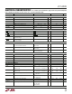
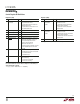
Register 2 (02h)
BIT NAME TYPE* DESCRIPTION
d7 Reserved R Not Used
d6 Reserved R Not Used
d5 Connection R/W Sets logic requirements for
Requirement downstream buses to be connected
to upstream bus
0 = Bus Logic State bits (see register
3) of buses to be connected must be
high for connection to occur (default)
1 = Connect regardless of
downstream logic state
d4 Reserved R Not Used
d3 Reserved R Not Used
d2 Mass Write Enable R/W Enable Mass Write Address using
address (1011 110)b
0 = Disable Mass Write
1 = Enable Mass Write (default)
d1 Timeout Mode Bit 1 R/W Stuck Low Timeout Set Bit 1**
d0 Timeout Mode Bit 0 R/W Stuck Low Timeout Set Bit 0**
* For Type, “R/W” = Read Write, “R” = Read Only
**
TIMSET1 TIMSET0 TIMEOUT MODE
0 0 Timeout Disabled (Default)
0 1 Timeout After 30ms
1 0 Timeout After 15ms
1 1 Timeout After 7.5ms
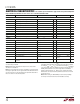
Register 3 (03h)
BIT NAME TYPE* DESCRIPTION
d7 Bus 1 FET State R/W Sets and indicates state of FET
switches connected to downstream
bus 1
0 = switch open (default)
1 = switch closed
d6 Bus 2 FET State R/W Sets and indicates state of FET
switches connected to downstream
bus 2
0 = switch open (default)
1 = switch closed
d5 Reserved R Not Used
d4 Reserved R Not Used
d3 Bus 1 Logic State R Indicates logic state of downstream
bus 1; only valid when disconnected
from upstream bus
†
0 = SDA1, SCL1 or both are below 1V
1 = SDA1 and SCL1 are both above
1V
d2 Bus 2 Logic State R Indicates logic state of downstream
bus 2; only valid when disconnected
from upstream bus
†
0 = SDA2, SCL2 or both are below 1V
1 = SDA2 and SCL2 are both above
1V
d1 Reserved R Not Used
d0 Reserved R Not Used
* For Type, “R/W” = Read Write, “R” = Read Only
†
These bits are meant to give the logic state of disconnected downstream
buses to the master, so that the master can choose not to connect to a low
downstream bus. A given bit is a “don’t care” if its associated downstream
bus is already connected to the upstream bus.
OPERATIO
U