
Datasheet

LTC4306
4306f
12
In all other cases, the LTC4306 communicates with the
master to resolve the fault. After the master broadcasts the
Alert Response Address (ARA), the LTC4306 will respond
with its address on the SDAIN line and release the ALERT
pin. The ALERT line will also be released if the LTC4306 is
addressed by the master.
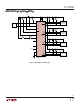
The ALERT signal will not be pulled low again until a
different type of fault has occurred or the original fault is
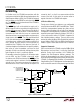
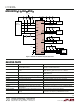
cleared and it occurs again. Figure 2 shows the details of
how the ALERT pin is set and reset. The downstream bus
connection fault and faults that occur on unconnected
downstream buses are grouped together and generate a
single signal to drive ALERT. The stuck low timeout fault
has its own dedicated pathway to ALERT; however, once
a stuck low occurs, another one will not occur until the first
one is cleared. For these reasons, once the master has
established the LTC4306 as the source of the fault, it
should read register 0 to determine the specific problem,
take action to solve the problem, and clear the fault
promptly. All faults are cleared by writing a dummy data
byte to register 0, which is a read-only register.
For example, assume that a fault occurs, the master sends
out the ARA, and the LTC4306 successfully writes
its address onto SDAIN and releases its ALERT pin. The
master reads register 0 and learns that the ALERT2 logic
state bit is low. The master now knows that a device on
downstream bus 2 has a fault and writes to register 3 to
connect to bus 2, so that it can communicate with the
source of the fault. At this point, the master writes to
register 0 to clear the LTC4306 fault register.
I
2
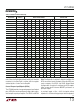
C Device Addressing
Twenty-seven distinct bus addresses are configurable
using the three state ADR0, ADR1 and ADR2 pins. Table 1
shows the correspondence between pin states and ad-
dresses. Note that address bits a6 and a5 are internally
configured to 1 and 0 respectively. In addition, the LTC4306
responds to two special addresses. Address (1011 101) is
a mass write used to write all LTC4306’s, regardless of
their individual address settings. The mass write can be
masked by setting the Mass Write Enable bit of register 2
to zero. Address (0001 100) is the SMBus Alert Response
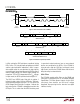
Address. Figure 3 shows data transfer over a 2-wire bus.
Supported Commands
Users must write to the LTC4306 using the SMBus Write
Byte protocol and read from it using the Read Byte
protocol. During fault resolution, the LTC4306 also
supports the Alert Response Address protocol. The
formats for these protocols are shown in Figure 4. Users
must follow the Write Byte protocol exactly to write to the
LTC4306; if a Repeated Start Condition is issued before a
Stop Condition, the LTC4306 ignores the attempted write,
and its control bits remain in their preexisting state. When
OPERATIO
U
D
4306 F02
V
CC
Q
WRITE
REGISTER 0
R
D
D
FAULT ON CONNECTED
DOWNSTREAM BUS
V
CC
Q
WRITE
REGISTER 0
FAULT ON DISCONNECTED
DOWNSTREAM BUS
DOWNSTREAM BUS
CONNECTION FAULT
ADDRESS LTC4306
STUCK BUS
LTC4306 RESPONDS
TO ARA
R
D
ALERT
Figure 2. Setting and Resetting the ALERT Pin