
Datasheet


LTC4309
10
4309fa
has disconnected the input and output busses due to a
bus stuck low condition. READY goes high when ENABLE
is high and start-up is complete. The pin is driven by an
open drain pull-down device capable of sinking 3mA
while holding 0.4V on the pin. Connect a resistor to the
bus pull-up supply to provide the pull-up.
FAULT Digital Output
This pin provides a digital flag which is low when SDA
or SCL is low for 30ms (typical). The pin is driven by an
open drain pull-down capable of sinking 3mA while hold-
ing 0.4V on the pin. Connect a resistor from FAULT to the
bus pull-up supply to provide the pull-up.
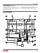
Live Insertion and Capacitance Buffering Application
Figures 4 and 5 illustrate applications of the LTC4309 that
take advantage of the LTC4309’s Hot Swap
TM
, capacitance
buffering and precharge features. If the I/O cards were
plugged directly into the backplane without the LTC4309
buffer, all of the backplane and card capacitances would
add directly together, making rise time and fall time re-
quirements difficult to meet. Placing an LTC4309 on the
edge of each card, however, isolates the card capacitance
from the backplane. For a given I/O card, the LTC4309
drives the capacitance of everything on the card and the
backplane must drive only the capacitance of the LTC4309,
which is less than 10pF.
Figure 4 shows the LTC4309 used in the typical staggered
connector application, where V
CC
and GND are the longest
“early power” pins. The “early power” pins ensure the
LTC4309 is initially powered and forcing a 1V precharge
voltage on the medium length SDA and SCL pins before
they contact to the backplane busses. Coupled with
ENABLE as the shortest pin, passively pulled to ground
by a resistor, the staggered approach provides additional
time for transients associated with live insertion to settle
before the LTC4309 can be enabled.
Figure 5 shows the LTC4309 in an application where all
of the pins have the same length. In this application, a
resistor is used to hold the ENABLE pin low during live
insertion, until the backplane control circuitry can enable
the device.
Repeater/Bus Extender Applications
Users who wish to connect two 2-wire systems separated
by a distance can do so by connecting two LTC4309s back-
to-back, as shown in Figure 6. The I
2
C specification allows
for 400pF maximum bus capacitance, severely limiting
the length of the bus. The SMBus specification places no
restriction on bus capacitance, but the limited impedances
of devices connected to the bus require systems to remain
small if rise time and fall time specifications are to be met.
In this situation, the differential ground voltage between
the two systems may limit the allowed distance, because
a valid logic low voltage with respect to the ground at one
end of the system may violate the allowed V
OL
specification
with respect to the ground at the other end. In addition,
the connection circuitry offset voltages of the back-to-
back LTC4309s add together, directly contributing to the
same problem.
Figure 7 further illustrates a repeater application. In
AdvancedTCA applications, the bus pull-up resistance can
be quite small. Since there is no effect on the offset due
OPERATION
APPLICATIONS INFORMATION
Hot Swap is a trademark of Linear Technology Corporation.
ENABLE
When the ENABLE pin is driven below 0.8V with respect
to the LTC4309’s ground, the input pin is disconnected
from the output pin and the READY pin is internally pulled
low. When the pin is driven above 2V, the part waits for
data transactions on both the input and output pins to be
complete (as described in the Start-Up section) before
connecting the two sides. At this time the internal pull-
down on READY releases.
A rising edge on ENABLE after a fault has occurred forces a
connection between SDAIN, SDAOUT and SCLIN, SCLOUT,
even if the bus stuck low conditions has not been cleared.
At this time, the 30ms timer is reset, but not disabled.