
Datasheet


LTC4311
5
4311fa
PIN FUNCTIONS
BUS1: Active Pull-up for Bus. Connect to either clock line
or data line for 2-wire bus.
BUS2: Active Pull-up for Bus. Connect to either clock line
or data line for 2-wire bus.
ENABLE: Device Enable Input. This is a 1V nominal digital
threshold input pin. For normal operation drive ENABLE
to a voltage greater than 1.5V. Driving ENABLE below the
0.4V threshold puts the device in a low (<5μA) current
shutdown mode and puts the BUS pins in a high imped-
ance state. If unused, connect to V
CC
.
EXPOSED PAD (DFN Package Only): Exposed Pad may
be left open or connected to device ground.
GND: Device Ground. Connect this pin to a ground plane
for best results.
V
CC
: Supply Voltage Input. Connect this pin to bus supply
and place a bypass capacitor of at least 0.01μF close to
V
CC
for best results.
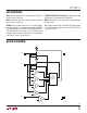
BLOCK DIAGRAM
–
+
–
+
–
+
–
+
–
+
V
THR
SLEW RATE
DETECTOR
CONTROL
LOGIC AND
INTERNAL SLEW
COMPARATOR
V
THR
V
CC
– 0.4
V
CC
– 0.4
1V
SLEW RATE
DETECTOR
5mA
BUS1 V
CC
GND
BUS2
ENABLE
5mA
4311 BD