
Datasheet

LTC4312
19
4312f
Information furnished by Linear Technology Corporation is believed to be accurate and reliable.
However, no responsibility is assumed for its use. Linear Technology Corporation makes no representa-
tion that the interconnection of its circuits as described herein will not infringe on existing patent rights.
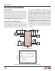
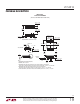
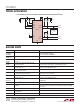
PACKAGE DESCRIPTION
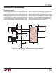
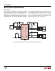
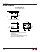
MS Package
16-Lead Plastic MSOP
(Reference LTC DWG # 05-08-1669 Rev Ø)
MSOP (MS16) 1107 REV Ø
0.53 p 0.152
(.021 p .006)
SEATING
PLANE
0.18
(.007)
1.10
(.043)
MAX
0.17 –0.27
(.007 – .011)
TYP
0.86
(.034)
REF
0.50
(.0197)
BSC
1615 1413121110
12345678
9
NOTE:
1. DIMENSIONS IN MILLIMETER/(INCH)
2. DRAWING NOT TO SCALE
3. DIMENSION DOES NOT INCLUDE MOLD FLASH, PROTRUSIONS OR GATE BURRS.
MOLD FLASH, PROTRUSIONS OR GATE BURRS SHALL NOT EXCEED 0.152mm (.006") PER SIDE
4. DIMENSION DOES NOT INCLUDE INTERLEAD FLASH OR PROTRUSIONS.
INTERLEAD FLASH OR PROTRUSIONS SHALL NOT EXCEED 0.152mm (.006") PER SIDE
5. LEAD COPLANARITY (BOTTOM OF LEADS AFTER FORMING) SHALL BE 0.102mm (.004") MAX
0.254
(.010)
0o – 6o TYP
DETAIL “A”
DETAIL “A”
GAUGE PLANE
5.23
(.206)
MIN
3.20 – 3.45
(.126 – .136)
0.889 p 0.127
(.035 p .005)
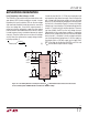
RECOMMENDED SOLDER PAD LAYOUT
0.305 p 0.038
(.0120 p .0015)
TYP
0.50
(.0197)
BSC
4.039 p 0.102
(.159 p .004)
(NOTE 3)
0.1016 p 0.0508
(.004 p .002)
3.00 p 0.102
(.118 p .004)
(NOTE 4)
0.280 p 0.076
(.011 p .003)
REF
4.90 p 0.152
(.193 p .006)