
Datasheet

LTC4312
13
4312f
APPLICATIONS INFORMATION
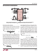
the LTC4312 can be cascaded with the LTC4303 and
LTC4307 if the LTC4312’s RTA turn-on voltage is set to be
0.8V (ACC low). The LTC4312 can be cascaded with the
LTC4301 and LTC4301L under all ACC settings as these
devices do not have RTAs. The LTC4312 can be cascaded
with the LTC4302, LTC4304, LTC4305 and LTC4306 if the
LTC4312’s RTAs are set to turn on at 0.8V (ACC low) or
under all ACC settings if the RTAs on the other bus buf-
fers are disabled. Finally, two LTC4312s can be cascaded
if their ACC pins are tied to the same state, HIGH, LOW
or open or if the ACC pin of one LTC4312 is tied high and
the other is left open.
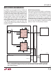
Radial Telecommunications
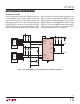
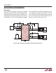
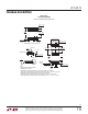
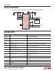
Figure 6 shows the use of the LTC4312 in a radial telecom-
munications application. Two Shelf Managers are wired to
communicate with slave I
2
C devices for redundancy. Each
Shelf Manager can have as many LTC4312s as required
depending on the number of boards in the system and
the desired radial/star confi guration. The ENABLE pins of
the LTC4312s inside only one Shelf Manager are asserted
high at any time. For simplicity, in Figure 6 only the SDA
pathway is shown. The SCL pathway is identical.
Figure 6. LTC4312s Confi gured for a Radially Connected Redundant Telecommunications Shelf Manager Application
in a 12 × 2 Arrangement. The ENABLE Pins on Only One of the Shelf Managers Are High at Any Time. Only the SDA
Path Is Shown for Simplicity
LTC4312 #1
GND
V
CC
3.3V
V
CC2
SHMC #1
SHMC #2
(IDENTICAL TO SHMC#1)
4312 F06
SDAOUT1
SDAOUT2
SDAIN
ENABLE1
ENABLE2
ACC
ENABLE1A
ENABLE2A
μP
R1
10k
BACKPLANE
IPMB-A
SDA1
IPMB-A
SDA24
IPMB-B
SDA1
SDA24
SDA1
FRU #1
FRU #24
3.3V
R2
10k
3.3V
ttt
ttt
ttt
LTC4312 #12
GND
V
CC
3.3V
V
CC2
SDAOUT1
SDAOUT2
SDAIN
ENABLE1
ENABLE2
ACC
ENABLE23A
ENABLE24A
R3
10k
3.3V
ttt
IPMB-A (×24)
IPMB-B (×24)
IPMB-B (×24)
IPMB-B
SDA24
ttt
SDA24
SDA1
ttt