
Datasheet

LTC4313-1/LTC4313-2/
LTC4313-3
3
4313123f
elecTrical characTerisTics
SYMBOL PARAMETER CONDITIONS MIN TYP MAX UNITS
Power Supply/Start-Up
V
CC
Input Supply Voltage
l
2.9 5.5 V
V
DD,BUS
2-Wire Bus Supply Voltage LTC4313-1, LTC4313-2
l
2.9 5.5 V
LTC4313-3
l
1.4 5.5 V
I
CC
Input Supply Current V
ENABLE
= V
CC
= 5.5V, V
SDAIN,SCLIN
= 0V
(Note 3)
l
6 8.1 10 mA
I
CC(DISABLED)
Input Supply Current V
ENABLE
= 0V, V
CC
= 5.5V,
V
SDAIN,SCLIN
= 0V
l
2.5 3.5 4.5 mA
V
TH_UVLO
V
CC
UVLO Threshold V
CC
Rising
l
2.55 2.7 2.85 V
V
CC_UVLO(HYST)
UVLO Threshold Hysteresis Voltage 200 mV
V
PRE
Precharge Voltage SDA, SCL Pins Open
l
0.8 1 1.2 V
Buffers
V
OS(SAT)
Buffer Offset Voltage I
OL
= 4mA, Driven V
SDA,SCL
= 50mV
l
100 190 280 mV
I
OL
= 500µA, Driven V
SDA,SCL
= 50mV
l
15 60 120 mV
V
OS
Buffer Offset Voltage I
OL
= 4mA, Driven V
SDA,SCL
= 200mV
l
50 120 180 mV
I
OL
= 500µA, Driven V
SDA,SCL
= 200mV
l
15 60 115 mV
V
IL, FALLING
Buffer Input Logic Low Voltage V
CC
= 2.9V, 3.3V, 5.5V
l
0.3•V
CC
0.33•V
CC
0.36•V
CC
V
∆V
IL(HYST)
V
IL
Hysteresis Voltage 50 mV
I
LEAK
Input Leakage Current SDA, SCL Pins = 5.5V, V
CC
= 5.5V, 0V
l
±10 µA
C
IN
Input Capacitance SDA, SCL Pins (Note 4)
l
10 pF
Rise Time Accelerators (LTC4313-1 and LTC4313-2 Only)
dV/dt
(RTA)
Minimum Slew Rate Requirement SDA, SCL Pins, V
CC
= 5V
l
0.1 0.2 0.4 V/µs
V
RTA(TH)
Rise Time Accelerator DC Threshold Voltage V
CC
= 5V
l
0.38 •V
CC
0.41•V
CC
0.44•V
CC
V
∆V
ACC
Buffers Off to Accelerator On Voltage SDA, SCL Pins, V
CC
= 5V
l
0.05•V
CC
0.07•V
CC
mV
I
RTA
Rise Time Accelerator Pull-Up Current SDA, SCL Pins, V
CC
= 5V (Note 5)
LTC4313-1
l
15
25
40
mA
LTC4313-2
l
1.5 2.5 3.5 mA
Enable/Control
V
EN(TH)
ENABLE Threshold Voltage
l
1 1.4 1.8 V
I
LEAK
ENABLE Leakage Current V
ENABLE
= 5.5V
l
0.1 ±10 µA
V
READY(OL)
READY Output Low Voltage I
READY
= 3mA, V
CC
= 5V
l
0.4 V
I
READY(OH)
READY Off Leakage Current V
CC
= V
READY
= 5V
l
0.1 ±5 µA
Stuck Low Timeout Circuitry
t
TIMEOUT
Bus Stuck Low Timer
l
35 45 55 ms
I
2
C Interface Timing
f
SCL(MAX)
I
2
C Frequency Max
l
400 kHz
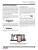
t
PDHL
SCL, SDA Fall Delay V
CC
= V
DD,BUS
= 5V, C
BUS
= 100pF,
R
BUS
= 10kΩ (Note 4)
130 250 ns
t
f
SCL, SDA Fall Times V
CC
= V
DD,BUS
= 5V, C
BUS
= 100pF,
R
BUS
= 10kΩ (Note 4)
20 300 ns
t
IDLE
Bus Idle Time
l
55 95 175 µs
The l denotes the specifications which apply over the full operating
temperature range, otherwise specifications are at T
A
= 25°C. V
CC
= 3.3V unless otherwise noted.
Note 1: Stresses beyond those listed under Absolute Maximum Ratings
may cause permanent damage to the device. Exposure to any Absolute
Maximum Rating condition for extended periods may affect device
reliability and lifetime.
Note 2: All currents into pins are positive and all voltages are referenced to
GND unless otherwise indicated.
Note 3: Test performed with SDA, SCL buffers active.
Note 4: Guaranteed by design and not tested.
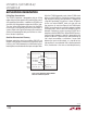
Note 5: Measured in a special DC mode with V
SDA,SCL
= V
RTA(TH)
+ 1V.
The transient I
RTA
during rising edges for the LTC4313-1 will depend on
the bus loading condition and the slew rate of the bus. The LTC4313-1’s
internal slew rate control circuitry limits the maximum bus rise rate to
75V/µs by controlling the transient I
RTA
.