
Datasheet


LTC4361-1/LTC4361-2
12
436112fb
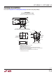
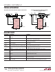
Figure 10. Layout for N-Channel MOSFET Configuration
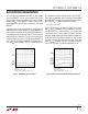
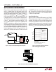
Figure 8. Setup for Testing 20V Plugged into 5V System Figure 9. Overvoltage Protection Waveforms
When 20V Plugged into 5V System
LOAD
436112 F08
OUT
M1
Si1470DH
C
OUT
IN
R
SENSE
L
IN
D1
B160
R
IN
20V
WALL
ADAPTER
5V
USB
R1
100k
LTC4361
GND
GATE
+
–
+
–
I
CABLE
SENSE
IN OUT
V
IN
20V/DIV
V
GATE
10V/DIV
V
OUT
5V/DIV
I
CABLE
10A/DIV
1µs/DIV
436112 F09
FIGURE 8 CIRCUIT
R
IN
= 150mΩ
L
IN
= 2µH, R
SENSE
= 25mΩ, LOAD = 10Ω
C
OUT
= 10µF (16V, SIZE 1210)
LTC4361
436112 F10
8
6
5
1
72
3
4
Si1470DH
OUT
IN
SUPPLY
GND
R
SENSE
1
2
3
6
5
4
Figure 8 shows a particularly severe situation which can
occur in a mobile device with dual power inputs. A 20V
wall adaptor is mistakenly hot-plugged into the 5V device
with the USB input already live. As shown in Figure 9, a
large current can build up in L
IN
to charge up C
OUT
. When
the N-channel MOSFET shuts off, the energy stored in L
IN
is dumped into C
OUT
, causing a large 40V input transient.
The LTC4361 limits this to a 1V rise in the output voltage.
If the ∆V
OUT
due to the discharge of the energy in L
IN
into
C
OUT
is not acceptable or the avalanche capability of the
MOSFET is exceeded, an additional external clamp such
as the SMAJ24A can be placed between IN and GND. C
OUT
is the decoupling capacitor of the protected circuits and
its value will largely be determined by their requirements.
Using a larger C
OUT
will work with L
IN
to slow down the
dV/dt at OUT, allowing time for the LTC4361 to shut off
the MOSFET before V
OUT
overshoots to a dangerous volt-
age. A larger C
OUT
also helps to lower the ∆V
OUT
due to
the discharge
of the energy in L
IN
if the MOSFET BV
DSS
is used as an input clamp.
Layout Considerations
Figure 10 shows an example PCB layout for the LTC4361
(TS8 package) with a single N-channel MOSFET (SC70
package) and a 0603 size sense resistor. Keep the traces
to the N-channel MOSFET wide and short. The PCB traces
associated with the power path through the N-channel
MOSFET should have low resistance. Use Kelvin connec-
tions to R
SENSE
for an accurate overcurrent threshold.
applicaTions inFormaTion