
Datasheet


1
LTC4414
4414fc
, LT, LTC and LTM are registered trademarks of Linear Technology Corporation.
PowerPath and ThinSOT are trademarks of Linear Technology Corporation. All other
trademarks are the property of their respective owners.
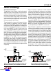
FORWARD VOLTAGE (V)
0.02
0
CURRENT (A)
8.0
3.6
CONSTANT
R
ON
4414 TA01b
0.5
CONSTANT
VOLTAGE
SCHOTTKY
DIODE
LTC4414
V
IN
GND
CTL
NC
SENSE
GATE
STAT
NC
LTC4414
C
OUT
TO LOAD
STATUS OUTPUT
LOW WHEN POWER
SUPPLY PRESENT
470k
4414 TA01
V
CC
UPS840
SUP75P03_07
BATTERY
CELL(S)
POWER
SUPPLY
INPUT
Automatic Switchover of Load Between a Battery and a Power Supply
APPLICATIO S
U
FEATURES
DESCRIPTIO
U
TYPICAL APPLICATIO
U
36V, Low Loss PowerPath
TM
Controller for Large PFETs
■
Designed Specifically to Drive Large Q
G
PFETs
■
Very Low Loss Replacement for Power Supply
OR’ing Diodes
■
3.5V to 36V AC/DC Adapter Voltage Range
■
Minimal External Components
■
Automatic Switching Between DC Sources
■
Low Quiescent Current: 30µA
■
3V to 36V Battery Voltage Range
■
Limited Reverse Battery Protection
■
MOSFET Gate Protection Clamp
■
Manual Control Input
■
Space Saving 8-Lead MSOP Package
■
High Current Power Path Switch
■
Industrial and Automotive Applications
■
Uninterruptable Power Supplies
■
Logic Controlled Power Switch
■
Battery Backup Systems
■
Emergency Systems with Battery Backups
The LTC
®
4414 controls an external P-channel MOSFET to
create a near ideal diode function for power switchover.
This permits highly efficient OR’ing of multiple power
sources for extended battery life and low self- heating. When
conducting, the voltage drop across the MOSFET is typi-
cally 20mV. For applications with a wall adapter or other aux-
iliary power source, the load is automatically disconnected
from the battery when the auxiliary source is connected.
Two or more LTC4414s may be interconnected to allow
switchover between multiple batteries or charging of mul-
tiple batteries from a single charger.
The wide supply operating range supports operation from
one to eight Li-Ion cells in series. The low quiescent
current (30µA typical) is independent of the load current.
The gate driver includes an internal voltage clamp for
MOSFET protection.
The STAT pin can be used to enable an auxiliary P-channel
MOSFET power switch when an auxiliary supply is
detected. This pin may also be used to indicate to a micro-
controller that an auxiliary supply is connected. The con-
trol (CTL) input enables the user to force the primary
MOSFET off and the STAT pin low.
The LTC4414 is available in a low profile 8-lead MSOP
package.
LTC4414 vs Schottky Diode Forward Voltage Drop
Downloaded from Arrow.com.