
Datasheet


LTC4415
1
4415fa
Typical applicaTion
FeaTures DescripTion
Dual 4A Ideal Diodes with
Adjustable Current Limit
The LTC
®
4415 contains two monolithic PowerPath ideal
diodes, each capable of supplying up to 4A with typical
forward conduction resistance of 50mΩ. The diode voltage
drops are regulated to 15mV during forward conduction at
low currents, extending the power supply operating range
and ensuring no oscillations during supply switchover.
Less than 1µA of reverse current flows from OUT to IN
making this device well suited for power supply ORing
applications.
The two ideal diodes are independently enabled and
prioritized using inputs EN1 and EN2. The output current
limits can be adjusted independently from 0.5A to 4A
using resistors on the CLIM pins. Furthermore, the ideal
diode currents can be monitored via CLIM pin voltages.
Open-drain status pins indicate when the ideal diodes are
forward conducting. When the die temperature approaches
thermal shutdown, or if the output load exceeds the cur-
rent limit threshold, the corresponding warning pins are
pulled low.
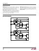
Prioritized Power Supply ORing
applicaTions
n
Dual 50mΩ Monolithic Ideal Diodes
n
1.7V to 5.5V Operating Range
n
Up to 4A Adjustable Current Limit for Each Diode
n
Low Reverse Leakage Current (1µA Max)
n
15mV Forward Drop in Regulation
n
Smooth Switchover in Diode ORing
n
Load Current Monitor
n
Precision Enable Thresholds to Set Switchover
n
Soft-Start to Limit Inrush Current on Start-Up
n
Status Pins to Indicate Forward Diode Conduction
n
Current and Thermal Limit with Warning
n
Thermally Enhanced 16-Lead MSOP and DFN
(3mm × 5mm) Packages
n
High Current PowerPath™ Switch
n
Battery and Wall Adapter Diode ORing
n
Backup Battery Diode ORing
n
Logic Controlled High Current Power Switch
n
Supercapacitor ORing
n
Multiple Battery Sharing
L, LT, LTC, LTM, Linear Technology and the Linear logo are registered trademarks and
PowerPath is a trademark of Linear Technology Corporation. All other trademarks are the
property of their respective owners.
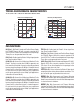
IDEAL
IDEAL
LTC4415
GND
EN1
4415 TA01a
4.7µF
TO
LOAD
100k
21.5k
124Ω124Ω
CLIM1
CLIM2
STAT1
WARN1
WARN2
STAT2
EN2
IN2
IN1 OUT1
OUT2
PRIMARY
POWER
SOURCE
SECONDARY
POWER
SOURCE
+
FORWARD VOLTAGE DROP (mV)
0
LOAD CURRENT (A)
3
4
400
4415 TA01b
2
1
0
100
200
300
500
CURRENT LIMIT
LTC4415
R
ON
= 50mΩ
SCHOTTKY
DIODE
MBRS410E
Forward Characteristics of LTC4415
vs MBRS410E Schottky