
Datasheet


LTC4415
10
4415fa
when the load current decreases below the current limit.
Power consumption in LTC4415 increases during opera-
tion in current limit due to the large voltage drop across
the PFET devices (P1 or P2).
Load Current Monitor
The current limit pins output 1/1000th of the ideal diode
output current. The voltage across the current limit resis-
tor can be measured to monitor the current through each
ideal diode as follows:
I
OUT
=1000 •
V
CLIM
R
CLIM
Note that the current monitor function via V
CLIM
is not
available when CLIM pins are grounded to use the fixed
internal current limit.
Soft-Start
An internal soft-start is included for each ideal diode to
minimize the start-up inrush current. When either of the
diodes start forward conduction, the load current ramps
from zero to the set current limit over a period of 2ms. The
soft-start can be monitored by observing the CLIM1 and
CLIM2 pin voltages when they are connected to grounded
resistors. Soft-start duration is reduced to 0.5ms (typical)
when the CLIM pins are grounded. In order to minimize
output droop during switchover between input sources
in power supply ORing applications, soft-start is disabled
when the output voltage is above 1.2V.
Forward Conduction Status Monitor
Active low open-drain output status signals, STAT1 and
STAT2, indicate the forward conduction status of each
ideal diode. With resistor pull-ups on these status pins,
a low voltage indicates forward conduction from input to
output, IN1/IN2 to OUT1/OUT2, respectively. The status
pins go to high impedance when the respective ideal diodes
are disabled, during reverse turn-off conditions, or during
thermal shutdown.
Thermal Warning and Shutdown
Thermal sensors within the LTC4415 monitor the die tem-
perature when either of the diodes are enabled. When the
die temperature exceeds the warning threshold (130°C),
the WARN1/WARN2 pins are pulled down with open-drain
NFETs while the LTC4415 continues to operate normally.
This gives some time for the user to reduce the load current
to avoid thermal shutdown. The warning signal is deas-
serted when the die temperature cools down below 115°C.
Thermal shutdown is triggered when the internal die
temperature increases beyond the fault threshold (160°C).
Status pins, STAT1/STAT2, are deasserted during thermal
shutdown to indicate the interruption in forward condi-
tion. Normal operation resumes when the die temperature
cools below 140°C. Note that prolonged operation at the
overtemperature condition degrades device reliability.
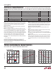
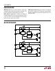
Figure 2 shows WARN followed by thermal shutdown
caused by an output short-circuit to ground. Time to
thermal shutdown varies depending on power dissipation,
ambient temperature and board layout. The output cur-
rent ramps up after the device cools down below 140°C,
but shuts down repeatedly as the device overheats due
to persistent short.
operaTion
Figure 2. Current Limit Warning and
Thermal Shutdown on Output Short Circuit
V
OUT
2V/DIV
I
OUT
2A/DIV
10ms/DIV
4415 F02
V
IN
= 3.6V
R
CLIM
= 124Ω
C
OUT
= 4.7µF
STAT
5V/DIV
WARN
5V/DIV
OUTPUT SHORTED
TO GND
RESTART DUE TO
THERMAL HYSTERESIS
THERMAL
SHUTDOWN
The thermal sensors are independent for each diode to
warn of, or shut down the heat generating path so that it
does not hinder the normal operation of the other path.
Depending on the amount of heat generated, the whole
die may still heat up and eventually shut down the other
channel.