
Datasheet


LTC4415
7
4415fa
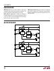
pin FuncTions
IN1 (Pins 1, 2): Diode 1 Anode and Positive Power Supply
for LTC4415. Bypass IN1 with a ceramic capacitor of at
least 4.7µF. Pins 1 and 2 are fused together on the package.
These pins can be grounded when not used.
EN1 (Pin 3): Enable Input for Diode 1. A high signal greater
than V
ENTH
enables Diode 1.
CLIM1 (Pin 4): Current Limit Adjust and Monitor Pin for
Diode 1. Connect a resistor from CLIM1 to ground to set
the current limit; the diode 1 current can then be monitored
by measuring the voltage on CLIM1 pin. A fixed 6A internal
current limit is active when this pin is shorted to ground.
Do not leave this pin open. Minimize stray capacitance
on this pin to generally less than 200pF (see Applications
Information for more details).
CLIM2 (Pin 5): Current Limit Adjust and Monitor Pin for
Diode 2. Connect a resistor from CLIM2 to ground to set
the current limit; the diode 2 current can then be monitored
by measuring the voltage on CLIM2 pin. A fixed 6A internal
current limit is active when this pin is shorted to ground.
Do not leave this pin open. Minimize stray capacitance
on this pin to generally less than 200pF (see Applications
Information for more details).
EN2 (Pin 6): Enable Input for Diode 2. A low signal less
than V
ENTH
enables Diode 2.
IN2 (Pins 7, 8): Diode 2 Anode and Positive Power Supply
for LTC4415. Bypass IN2 with a ceramic capacitor of at
least 4.7µF. Pins 7 and 8 are fused together on the package.
These pins can be grounded when not used.
OUT2 (Pins 9, 10): Diode 2 Cathode and Output of LTC4415.
Bypass OUT2 with a ceramic capacitor of at least 4.7µF.
Pins 9 and 10 are fused together on the package. Leave
these pins open when not used.
STAT2 (Pin 11): Status Indicator for Diode 2. Open-drain
output pulls down during forward diode conduction. This
pin can be left open or grounded when not used.
WARN2 (Pin 12): Overcurrent and Thermal Warning
Indicator for Diode 2. Open-drain output pulls down when
diode 2 current exceeds its current limit or die temperature
is close to thermal shutdown.
WARN1 (Pin 13): Overcurrent and Thermal Warning
Indicator for Diode 1. Open-drain output pulls down when
diode 1 current exceeds its current limit or die temperature
is close to thermal shutdown.
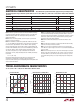
Power Loss vs Output Current Efficiency vs Output Current
Typical perForMance characTerisTics
T
A
= 25°C, V
IN1
= V
IN2
= 3.6V, R
CLIM
= 250Ω unless otherwise noted.
OUTPUT CURRENT (A)
0
POWER LOSS (W)
0.4
0.6
4
4415 G21
0.2
0
1
2
3
1.0
0.8
125°C
25°C
–40°C
R
CLIM
= 124Ω
OUTPUT CURRENT (A)
0
90
EFFICIENCY (%)
91
93
94
95
100
97
1
2
4415 G22
92
98
99
96
3
4
125°C
25°C
–40°C
R
CLIM
= 124Ω