
Datasheet


LTC4415
8
4415fa
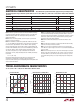
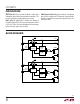
block DiagraM
GATE
DRIVER
CURRENT
LIMIT
TEMPERATURE
SENSOR
IN1
3
13
EN1
UVLO1
OUT1
WARN1
4
CLIM1
OUT1
15, 16
1, 2
P1
P2
14
STAT1
GATE
DRIVER
CURRENT
LIMIT
TEMPERATURE
SENSOR
IN2
6
12
EN2
UVLO2
OUT2
WARN2
5
CLIM2
OUT2
4415 BD
9, 10
7, 8
11
STAT2
I
OUT1
1000
I
OUT2
1000
pin FuncTions
STAT1 (Pin 14): Status Indicator for Diode 1. Open-drain
output pulls down during forward diode conduction. This
pin can be left open or grounded when not used.
OUT1 (Pins 15, 16): Diode 1 Cathode and Output of
LTC4415. Bypass OUT1 with a ceramic capacitor of at least
4.7µF. Pins 15 and 16 are fused together on the package.
Leave these pins open when not used.
GND (Exposed Pad Pin 17): Device Ground. The exposed
pad must be soldered to PCB ground to provide both
electrical connection to ground and good thermal con-
ductivity to PCB.