
Datasheet


LTC486
10
486fc
APPLICATIONS INFORMATION
The coupling capacitor allows high frequency energy to flow
to the termination, but blocks DC and low frequencies. The
dividing line between high and low frequency depends on
the length of the cable. The coupling capacitor must pass
frequencies above the point where the line represents an
electrical one-tenth wavelength. The value of the coupling
capacitor should therefore be set at 16.3pF per foot of cable
length for 120Ω cables. With the coupling capacitors in
place, power is consumed only on the signal edges, not
when the driver output is idling at a 1 or 0 state. A 100nF
capacitor is adequate for lines up to 4000 feet in length.
Be aware that the power savings start to decrease once
the data rate surpasses 1/(120Ω × C).
486 F11
140Ω
RECEIVER
RX
5V
1.5k
RECEIVER
RX
5V
110Ω
130Ω110Ω 130Ω
120Ω
RECEIVER
RX
C
5V
100k
1.5k
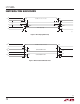
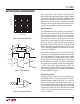
Figure 11. Forcing “0” When All Drivers Are Off
Receiver Open-Circuit Fail-Safe
Some data encoding schemes require that the output of
the receiver maintains a known state (usually a logic 1)
when the data is finished transmitting and all drivers on
the line are forced into three-state. All LTC RS485 receivers
have a fail-safe feature which guarantees the output to be
in a logic 1 state when the receiver inputs are left floating
(open-circuit). However, when the cable is terminated with
120Ω, the differential inputs to the receiver are shorted
together, not left floating.
If the receiver output must be forced to a known state, the
circuits of Figure 11 can be used.
The termination resistors are used to generate a DC bias
which forces the receiver output to a known state, in this
case a logic 0. The first method consumes about 208mW
and the second about 8mW. The lowest power solution is to
use an AC termination with a pull-up resistor. Simply swap
the receiver inputs for data protocols ending in logic 1.
Fault Protection
All of LTC’s RS485 products are protected against ESD
transients up to ±2kV using the human body model
(100pF, 1.5kΩ). However, some applications need greater
protection. The best protection method is to connect a
bidirectional TransZorb from each line side pin to ground
(Figure 12).
A TransZorb is a silicon transient voltage suppressor that
has exceptional surge handling capabilities, fast response
time, and low series resistance. They are available from
General Semiconductor Industries and come in a variety
of breakdown voltages and prices. Be sure to pick a break-
down voltage higher than the common-mode voltage
required for your application (typically 12V). Also, don’t
forget to check how much the added parasitic capacitance
will load down the bus.
486 F12
120Ω
DRIVER
Z
Y
Figure 12. ESD Protection