
Datasheet


LTC486
8
486fc
Typical Application
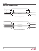
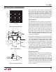
A typical connection of the LTC486 is shown in Figure 6.
A twisted pair of wires connect up to 32 drivers and
receivers for half duplex data transmission. There are no
restrictions on where the chips are connected to the wires,
and it isn’t necessary to have the chips connected at the
ends. However, the wires must be terminated only at the
ends with a resistor equal to their characteristic impedance,
typically 120Ω. The optional shields around the twisted
pair help reduce unwanted noise, and are connected to
GND at one end.
Thermal Shutdown
The LTC486 has a thermal shutdown feature which protects
the part from excessive power dissipation. If the outputs
of the driver are accidently shorted to a power supply or
low impedance source, up to 250mA can flow through
the part. The thermal shutdown circuit disables the driver
outputs when the internal temperature reaches 150°C and
turns them back on when the temperature cools to 130°C.
If the outputs of two or more LTC486 drivers are shorted
directly, the driver outputs cannot supply enough current
to activate the thermal shutdown. Thus, the thermal shut-
down circuit will not prevent contention faults when two
drivers are active on the bus at the same time.
Cable and Data Rate
The transmission line of choice for RS485 applications is
a twisted pair. There are coaxial cables (twinaxial) made
for this purpose that contain straight pairs, but these are
less flexible, more bulky, and more costly than twisted
pairs. Many cable manufacturers offer a broad range of
120Ω cables designed for RS485 applications.
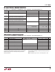
Losses in a transmission line are a complex combination of
DC conductor loss, AC losses (skin effect), leakage, and AC
losses in the dielectric. In good polyethylene cables such
as the Belden 9841, the conductor losses and dielectric
losses are of the same order of magnitude, with relatively
low overall loss (Figure 7).
APPLICATIONS INFORMATION
Figure 7. Attenuation vs Frequency for Belden 9841
Figure 6. Typical Connection
EN
12
EN
4
486 F06
120Ω
DX
1
2
3
SHIELD
120Ω
RX
RX
SHIELD
3
DX
EN
12
EN
4
2
EN
EN
4
1
2
3
RX
RX
3
DX
EN
12
EN
4
1
DX
1/4 LTC4881/4 LTC486
1/4 LTC4881/4 LTC486
2
1
12
FREQUENCY (MHz)
0.1
0.1
LOSS PER 100 FT (dB)
1
10
1 10 100
486 F07