
Datasheet


LTC486
9
486fc
APPLICATIONS INFORMATION
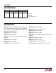
When using low loss cables, Figure 8 can be used as a
guideline for choosing the maximum line length for a given
data rate. With lower quality PVC cables, the dielectric loss
factor can be 1000 times worse. PVC twisted pairs have
terrible losses at high data rates (>100kbs) and greatly
reduce the maximum cable length. At low data rates how-
ever, they are acceptable and much more economical.
Cable Termination
The proper termination of the cable is very important. If
the cable is not terminated with its characteristic imped-
ance, distorted waveforms will result. In severe cases,
distorted (false) data and nulls will occur. A quick look
at the output of the driver will tell how well the cable is
terminated. It is best to look at a driver connected to the
end of the cable, since this eliminates the possibility of
getting reflections from two directions. Simply look at the
driver output while transmitting square wave data. If the
cable is terminated properly, the waveform will look like
a square wave (Figure 9).
If the cable is loaded excessively (e.g., 47Ω), the signal
initially sees the surge impedance of the cable and jumps
to an initial amplitude. The signal travels down the cable
and is reflected back out of phase because of the mister-
mination. When the reflected signal returns to the driver,
the amplitude will be lowered. The width of the pedestal
is equal to twice the electrical length of the cable (about
1.5ns/ft). If the cable is lightly loaded (e.g., 470Ω), the
signal reflects in phase and increases the amplitude at the
driver output. An input frequency of 30kHz is adequate for
tests out to 4000 ft. of cable.
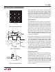
AC Cable Termination
Cable termination resistors are necessary to prevent un-
wanted reflections, but they consume power. The typical
differential output voltage of the driver is 2V when the
cable is terminated with two 120Ω resistors. When no
data is being sent 33mA of DC current flows in the cable.
This DC current is about 220 times greater than the supply
current of the LTC486. One way to eliminate the unwanted
current is by AC coupling the termination resistors as
shown in Figure 10.
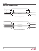
Figure 8. Cable Length vs Data Rate
DATA RATE (bps)
10k
10
CABLE LENGTH (FT)
100
1k
10k
100k 1M 10M
486 F08
2.5M
Figure 9. Termination Effects
Rt
DRIVERDX RECEIVER RX
Rt = 120Ω
Rt = 47Ω
Rt = 470Ω
486 F09
PROBE HERE
486 F10
C = LINE LENGTH (FT) × 16.3pF
120Ω
RECEIVER
RX
C
Figure 10. AC Coupled Termination