
Datasheet


LTC487
8
487fc
applicaTions inForMaTion
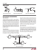
AC Cable Termination
Cable termination resistors are necessary to prevent un-
wanted reflections, but they consume power. The typical
differential output voltage of the driver is 2V when the
cable is terminated with two 120Ω resistors, causing
33mA of DC current to flow in the cable when no data is
being sent. This DC current is about 220 times greater than
the supply current of the LTC487. One way to eliminate
the unwanted current is by AC coupling the termination
resistors as shown in Figure 10.
LTC487 TA11
C = LINE LENGTH (FT) s 16.3pF
120Ω
RECEIVER
RX
C
Figure 10. AC-Coupled Termination
The coupling capacitor must allow high-frequency energy
to flow to the termination, but block DC and low frequen-
cies. The dividing line between high and low frequency
depends on the length of the cable. The coupling ca-
pacitor must pass frequencies above the point where the
line represents an electrical one-tenth wavelength. The
value of the coupling capacitor should therefore be set at
16.3pF per foot of cable length for 120Ω cables. With the
coupling capacitors in place, power is consumed only
on the signal edges, and not when the driver output is
idling at a 1 or 0 state. A 100nF capacitor is adequate for
lines up to 4000 feet in length. Be aware that the power
savings start to decrease once the data rate surpasses
1/(120Ω • C).
Receiver Open-Circuit Fail-Safe
Some data encoding schemes require that the output of
the receiver maintains a known state (usually a logic 1)
when the data is finished transmitting and all drivers on
the line are forced into three-state. All LTC RS485 receivers
have a fail-safe feature which guarantees the output to be
in a logic 1 state when the receiver inputs are left floating
(open-circuit). However, when the cable is terminated with
120Ω, the differential inputs to the receiver are shorted
together, not left floating. Because the receiver has about
70mV of hysteresis, the receiver output will maintain the
last data bit received.
If the receiver output must be forced to a known state, the
circuits of Figure 11 can be used.
LTC487 TA12
140Ω
RECEIVER
RX
5V
1.5k
RECEIVER
RX
5V
110Ω
130Ω110Ω 130Ω
120Ω
RECEIVER
RX
C
5V
100k
1.5k
Figure 11. Forcing ‘0’ When All Drivers Are Off
The termination resistors are used to generate a DC
bias which forces the receiver output to a known state,
in this case a logic 0. The first method consumes about
208mW and the second about 8mW. The lowest power
solution is to use an AC termination with a pull-up resis-
tor. Simply swap the receiver inputs for data protocols
ending in logic 1.
Fault Protection
All of LTC’s RS485 products are protected against ESD
transients up to 2kV using the human body model
(100pF, 1.5kΩ). However, some applications need more
protection. The best protection method is to connect a
bidirectional TransZorb from each line side pin to ground
(Figure 12).