
Datasheet


LTC487
6
487fc
TesT circuiT
applicaTions inForMaTion
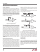
LTC487 TA02
A
B
R
R
OD
V
OC
V
DRIVER 1
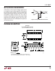
LTC487 TA03
DI
A
B
EN12
R
DIFF
C
L1
C
L2
LTC487 TA04
OUTPUT
UNDER TEST
C
L
S1
500
CC
V
Ω
S2
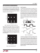
Figure 5. Driver Timing Test Load #2Figure 4. Driver Timing Test CircuitFigure 3. Driver DC Test Load
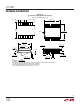
Typical Application
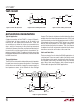
A typical connection of the LTC487 is shown in Figure 6.
A twisted pair of wires connect up to 32 drivers and
receivers for half duplex data transmission. There are
no restrictions on where the chips are connected to the
wires, and it isn’t necessary to have the chips connected
at the ends. However, the wires must be terminated only at
the ends with a resistor equal to their characteristic im-
pedance, typically 120Ω. The optional shields around the
twisted pair help reduce unwanted noise, and are connected
to GND at one end.
Thermal Shutdown
The LTC487 has a thermal shutdown feature which protects
the part from excessive power dissipation. If the outputs
of the driver are accidently shorted to a power supply or
low impedance source, up to 250mA can flow through
the part. The thermal shutdown circuit disables the driver
outputs when the internal temperature reaches 150°C and
turns them back on when the temperature cools to 130°C.
If the outputs of two or more LTC487 drivers are shorted
directly, the driver outputs can not supply enough cur-
rent to activate the thermal shutdown. Thus, the thermal
shutdown circuit will not prevent contention faults when
two drivers are active on the bus at the same time.
Cable and Data Rate
The transmission line of choice for RS485 applications is
a twisted pair. There are coaxial cables (twinaxial) made
for this purpose that contain straight pairs, but these are
less flexible, more bulky, and more costly than twisted
pairs. Many cable manufacturers offer a broad range of
120Ω cables designed for RS485 applications.
EN12
4
LTC487 • TA07
120Ω
DX
1
2
3
SHIELD
120Ω
RX
RX
SHIELD
3
DX
EN12
4
2
EN12
4
1
2
3
RX
RX
3
DX
EN12
4
1
DX
1/4 LTC4891/4 LTC487
1/4 LTC4891/4 LTC487
2
1
Figure 6. Typical Connection