
Datasheet

LTC488/LTC489
9
4889fb
APPLICATIONS INFORMATION
4889 F10
110Ω
RX
130Ω
130Ω 110Ω
5V
RX
RECEIVER
1.5k
120Ω
5V
1.5k
RX
120Ω
5V
C
100k
RECEIVER
RECEIVER
4889 F11
120Ω
DRIVER
Y
Z
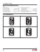
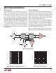
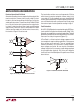
Receiver Open-Circuit Fail-Safe
Some data encoding schemes require that the output of the
receiver maintains a known state (usually a logic 1) when
the data is fi nished transmitting and all drivers on the line
are forced in three-state. The receiver of the LTC488/LTC489
has a fail-safe feature which guarantees the output to be
in a logic 1 state when the receiver inputs are left fl oating
(open-circuit). When the input is terminated with 120Ω
and the receiver output must be forced to a known state,
the circuits of Figure 10 can be used.
The termination resistors are used to generate a DC bias
which forces the receiver output to a known state, in this
case a logic 0. The fi rst method consumes about 208mW
and the second about 8mW. The lowest power solution is to
use an AC termination with a pullup resistor. Simply swap
the receiver inputs for data protocols ending in logic 1.
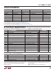
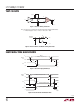
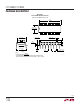
Fault Protection
All of LTC’s RS485 products are protected against ESD tran-
sients up to 2kV using the human body model (100pF, 1.5k).
However, some applications need more protection. The best
protection method is to connect a bidirectional TransZorb
®
from each line side pin to ground (Figure 11).
A TransZorb is a silicon transient voltage suppressor that
has exceptional surge handling capabilities, fast response
time, and low series resistance. They are available from
General instruments, GSI, and come in a variety of break-
down voltages and prices. Be sure to pick a breakdown
voltage higher than the common mode voltage required
for your application (typically 12V). Also, don’t forget to
check how much the added parasitic capacitance will load
down the bus.
Figure 11. ESD Protection with TransZorbs
Figure 10. Forcing “0” When All Drivers Are Off