
Datasheet
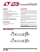


LTC488/LTC489
7
4889fb
Typical Application
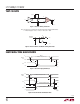
A typical connection of the LTC488/LTC489 is shown in
Figure 5. Two twisted-pair wires connect up to 32 driver/
receiver pairs for half-duplex data transmission. There are
no restrictions on where the chips are connected to the
wires, and it isn’t necessary to have the chips connected
at the ends. However, the wires must be terminated only
at the ends with a resistor equal to their characteristic
impedance, typically 120Ω. The input impedance of a
receiver is typically 20k to GND, or 0.5 unit RS485 load,
so in practice 50 to 60 transceivers can be connected to
the same wires. The optional shields around the twisted-
pair help reduce unwanted noise, and are connected to
GND at one end.
Cables and Data Rate
The transmission line of choice for RS485 applications is a
twisted-pair. There are coaxial cables (twinaxial) made for
this purpose that contain straight-pairs, but these are less
fl exible, more bulky, and more costly than twisted-pairs.
Many cable manufacturers offer a broad range of 120Ω
cables designed for RS485 applications.
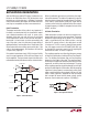
Losses in a transmission line are a complex combination
of DC conductor loss, AC losses (skin effect), leakage, and
AC losses in the dielectric. In good polyethylene cable such
as the Belden 9841, the conductor losses and dielectric
losses are of the same order of magnitude, leading to
relatively low overall loss (Figure 6).
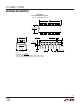
When using low loss cables, Figure 7 can be used as a
guideline for choosing the maximum line length for a given
APPLICATIONS INFORMATION
Figure 5. Typical Connection
Figure 7. Cable Length vs Data RateFigure 6. Attenuation vs Frequency for Belden 9841
120Ω
120Ω
3
RX
2
1
4889 F05
DX
1
3
SHIELD
RX
EN
DX
1/4 LTC486
12
SHIELD
4
12
3
2
DX
DX
1/4 LTC486
1
EN
1/4 LTC488 OR
1/4 LTC489
RX
3
1
2
4
RX
1/4 LTC488 OR
1/4 LTC489
EN
EN
FREQUENCY (MHz)
0.1
0.1
LOSS PER 100 FT (dB)
1
10
1 10 100
4889 F06
DATA RATE (bps)
10k
10
CABLE LENGTH (FT)
100
1k
10k
100k 1M 10M
4889 F07
2.5M