
Datasheet


LTC488/LTC489
8
4889fb
data rate. With lower quality PVC cables, the dielectric loss
factor can be 1000 times worse. PVC twisted-pairs have
terrible losses at high data rates (> 100kbps), and greatly
reduce the maximum cable length. At low data rates how-
ever, they are acceptable and much more economical.
Cable Termination
The proper termination of the cable is very important. If
the cable is not terminated with its characteristic imped-
ance, distorted waveforms will result. In severe cases,
distorted (false) data and nulls will occur. A quick look
at the output of the driver will tell how well the cable is
terminated. It is best to look at a driver connected to the
end of the cable, since this eliminates the possibility of
getting refl ections from two directions. Simply look at the
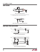
driver output while transmitting square wave data. If the
cable is terminated properly, the waveform will look like
a square wave (Figure 8).
If the cable is loaded excessively (47Ω), the signal initially
sees the surge impedance of the cable and jumps to an
initial amplitude. The signal travels down the cable and is
refl ected back out of phase because of the mistermination.
When the refl ected signal returns to the driver, the ampli-
tude will be lowered. The width of the pedestal is equal to
twice the electrical length of the cable (about 1.5ns/foot).
If the cable is lightly loaded (470Ω), the signal refl ects
in phase and increases the amplitude at the drive output.
An input frequency of 30kHz is adequate for tests out to
4000 ft. of cable.
AC Cable Termination
Cable termination resistors are necessary to prevent un-
wanted refl ections, but they consume power. The typical
differential output voltage of the driver is 2V when the
cable is terminated with two 120Ω resistors, causing
33mA of DC current to fl ow in the cable when no data
is being sent. This DC current is about 60 times greater
than the supply current of the LTC488/LTC489. One way
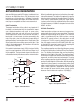
to eliminate the unwanted current is by AC coupling the
termination resistors as shown in Figure 9.
The coupling capacitor must allow high frequency energy
to fl ow to the termination, but block DC and low frequen-
cies. The dividing line between high and low frequency
depends on the length of the cable. The coupling capaci-
tor must pass frequencies above the point where the line
represents an electrical one-tenth wavelength. The value
of the coupling capacitor should therefore be set at 16.3pF
per foot of cable length for 120Ω cables. With the coupling
capacitors in place, power is consumed only on the signal
edges, and not when the driver output is idling at a 1 or 0
state. A 100nF capacitor is adequate for lines up to 4000
feet in length. Be aware that the power savings start to
decrease once the data rate surpasses 1/(120Ω)(C).
APPLICATIONS INFORMATION
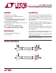
Figure 8. Termination Effects
Figure 9. AC-Coupled Termination
4889 F08
DX
PROBE HERE
Rt = 120Ω
Rt = 47Ω
Rt = 470Ω
Rt
RX
RECEIVER
DRIVER
488/9 F09
C = LINE LENGTH (FT)(16.3pF)
120Ω
C
RX
RECEIVER