
Datasheet


LTC490
6
490fb
Typical Application
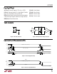
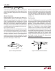
A typical connection of the LTC490 is shown in Figure 5.
Two twisted-pair wires connect two driver/receiver pairs
for full duplex data transmission. Note that the driver and
receiver outputs are always enabled. If the outputs must
be disabled, use the LTC491.
There are no restrictions on where the chips are con-
nected, and it isn’t necessary to have the chips connected
at the ends of the wire. However, the wires must be
terminated only at the ends with a resistor equal to their
characteristic impedance, typically 120Ω. Because only
one driver can be connected on the bus, the cable can be
terminated only at the receiving end. The optional shields
around the twisted pair help reduce unwanted noise, and
are connected to GND at one end.
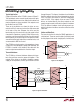
The LTC490 can also be used as a line repeater as shown
in Figure 6. If the cable length is longer than 4000 feet, the
LTC490 is inserted in the middle of the cable with the
receiver output connected back to the driver input.
Thermal Shutdown
The LTC490 has a thermal shutdown feature which pro-
tects the part from excessive power dissipation. If the
outputs of the driver are accidently shorted to a power
supply or low impedance, source, up to 250mA can flow
through the part. The thermal shutdown circuit disables
the driver outputs when the internal temperature reaches
150°C and turns them back on when the temperature
cools to 130°C. If the outputs of two or more LTC490
drivers are shorted directly, the driver outputs can not
supply enough current to activate the thermal shutdown.
Thus, the thermal shutdown circuit will not prevent con-
tention faults when two drivers are active on the bus at the
same time.
Cables and Data Rate
The transmission line of choice for RS485 applications is
a twisted pair. There are coaxial cables (twinaxial) made
for this purpose that contain straight pairs, but these are
Figure 5. Typical Connection
Figure 6. Line Repeater
APPLICATIO S I FOR ATIO
WUUU
LTC490 • F05
120Ω
120Ω
SHIELD
LTC490
DRIVER
RECEIVER
LTC490
DRIVER
DX
RX
DX
RX
2
3
5
6
7
8
RECEIVER
0.01µF
1
4
5V
SHIELD
8
7
6
5
0.01µF
5V
4
2
3
1
+
+
LTC490 • F06
120Ω
LTC490
DRIVERDX
RX
2
3
5
6
7
8
RECEIVER DATA IN
DATA OUT