
Datasheet

7
LTC490
490fb
less flexible, more bulky, and more costly than twisted
pairs. Many cable manufacturers offer a broad range of
120Ω cables designed for RS485 applications.
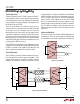
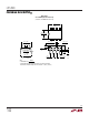
Losses in a transmission line are a complex combination
of DC conductor loss, AC losses (skin effect), leakage and
AC losses in the dielectric. In good polyethylene cables
such as the Belden 9841, the conductor losses and
dielectric losses are of the same order of magnitude,
leading to relatively low overall loss (Figure 7).
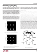
When using low loss cables, Figure 8 can be used as a
guideline for choosing the maximum line length for a given
data rate. With lower quality PVC cables, the dielectric loss
factor can be 1000 times worse. PVC twisted pairs have
APPLICATIO S I FOR ATIO
WUUU
terrible losses at high data rates (>100kbs), and greatly
reduce the maximum cable length. At low data rates
however, they are acceptable and much more economical.
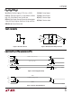
Cable Termination
The proper termination of the cable is very important.
If the cable is not terminated with its characteristic
impedance, distorted waveforms will result. In severe
cases, distorted (false) data and nulls will occur.
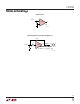
A quick look at the output of the driver will tell how well the
cable is terminated. It is best to look at a driver connected
to the end of the cable, since this eliminates the possibility
of getting reflections from two directions. Simply look at
the driver output while transmitting square wave data. If
the cable is terminated properly, the waveform will look
like a square wave (Figure 9). If the cable is loaded
excessively (47Ω), the signal initially sees the surge
impedance of the cable and jumps to an initial amplitude.
The signal travels down the cable and is reflected back out
of phase because of the mistermination. When the re-
flected signal returns to the driver, the amplitude will be
lowered. The width of the pedestal is equal to twice the
electrical length of the cable (about 1.5ns/foot). If the
Figure 7. Attenuation vs Frequency for Belden 9841
Figure 8. RS485 Cable Length Specification. Applies for 24
Gauge, Polyethylene Dielectric Twisted Pair Figure 9. Termination Effects
FREQUENCY (MHz)
0.1
0.1
LOSS PER 100 FT (dB)
1.0
10
1.0 10 100
LTC490 • F07
DATA RATE (bps)
10k
10
CABLE LENGTH (FT)
100
1k
10k
100k 1M 10M
LTC490 • F08
2.5M
Rt
DRIVERDX RECEIVER RX
Rt = 120Ω
Rt = 47Ω
Rt = 470Ω
LTC490 • F09
PROBE HERE