
Datasheet


LTC490
8
490fb
cable is lightly loaded (470Ω), the signal reflects in phase
and increases the amplitude at the driver output. An input
frequency of 30kHz is adequate for tests out to 4000 feet
of cable.
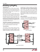
AC Cable Termination
Cable termination resistors are necessary to prevent un-
wanted reflections, but they consume power. The typical
differential output voltage of the driver is 2V when the
cable is terminated with two 120Ω resistors, causing
33mA of DC current to flow in the cable when no data is
being sent. This DC current is about 60 times greater than
the supply current of the LTC490. One way to eliminate the
unwanted current is by AC coupling the termination resis-
tors as shown in Figure 10.
The coupling capacitor must allow high frequency energy
to flow to the termination, but block DC and low frequen-
cies. The dividing line between high and low frequency
depends on the length of the cable. The coupling capacitor
must pass frequencies above the point where the line
represents an electrical one-tenth wavelength. The value
of the coupling capacitor should therefore be set at 16.3pF
per foot of cable length for 120Ω cables.
APPLICATIO S I FOR ATIO
WUUU
With the coupling capacitors in place, power is consumed
only on the signal edges, and not when the driver output
is idling at a 1 or 0 state. A 100nF capacitor is adequate for
lines up to 4000 feet in length. Be aware that the power
savings start to decrease once the data rate surpasses
1/(120Ω × C).
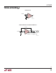
Fault Protection
All of LTC’s RS485 products are protected against ESD
transients up to 2kV using the human body model (100pF,
1.5kΩ). However, some applications need more
protection. The best protection method is to connect a
bidirectional TransZorb
®
from each line side pin to ground
(Figure 11). A TransZorb is a silicon transient voltage
suppressor that has exceptional surge handling capabili-
ties, fast response time, and low series resistance. They
are available from General Instruments, GSI and come in
a variety of breakdown voltages and prices. Be sure to pick
a breakdown voltage higher than the common mode
voltage required for your application (typically 12V). Also,
don’t forget to check how much the added parasitic
capacitance will load down the bus.
TransZorb is a registered trademark of General Instruments, GSI
Figure 10. AC Coupled Termination Figure 11. ESD Protection with TransZorbs
LTC490 • F10
120Ω
RECEIVER
RX
C
C = LINE LENGTH (FT) × 16.3pF
LTC490 • F11
120Ω
DRIVER
Z
Y