
Datasheet
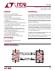

7
LTC491
491fa
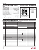
Typical Application
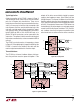
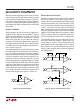
A typical connection of the LTC491 is shown in Figure 9.
Two twisted-pair wires connect up to 32 driver/receiver
pairs for full duplex data transmission. There are no
restrictions on where the chips are connected to the wires,
and it isn’t necessary to have the chips connected at the
ends. However, the wires must be terminated only at the
ends with a resistor equal to their characteristic imped-
ance, typically 120Ω. The input impedance of a receiver is
typically 20kΩ to GND, or 0.6 unit RS-485 load, so in
practice 50 to 60 transceivers can be connected to the
same wires. The optional shields around the twisted pair
help reduce unwanted noise, and are connected to GND at
one end.
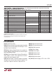
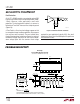
The LTC491 can also be used as a line repeater as shown
in Figure 10. If the cable length is longer than 4000 feet, the
LTC491 is inserted in the middle of the cable with the
receiver output connected back to the driver input.
Thermal Shutdown
The LTC491 has a thermal shutdown feature which pro-
tects the part from excessive power dissipation. If the
outputs of the driver are accidently shorted to a power
supply or low impedance source, up to 250mA can flow
through the part. The thermal shutdown circuit disables
the driver outputs when the internal temperature reaches
150°C and turns them back on when the temperature cools
to 130°C. If the outputs of two or more LTC491 drivers are
shorted directly, the driver outputs can not supply enough
current to activate the thermal shutdown. Thus, the ther-
mal shutdown circuit will not prevent contention faults
when two drivers are active on the bus at the same time.
APPLICATIO S I FOR ATIO
WUUU
Figure 9. Typical Connection
Figure 10. Line Repeater
LTC491 • F09
120Ω
120Ω
LTC491
DRIVER
RECEIVER
LTC491
DRIVER
DX
RX
DX
RX
2
5
9
10
11
12
RECEIVER
9
10
11
12
5
2
120Ω
3
4
3
4
120Ω
RECEIVER
LTC491
DRIVER
9 10 11 12
5
4
3
2
DX RX
LTC491 • F10
120Ω
LTC491
DRIVERDX
RX
2
5
9
10
11
12
RECEIVER DATA IN
DATA OUT
3
4
120Ω