
Datasheet

9
LTC491
491fa
U
S
A
O
PP
L
IC
AT
I
WU
U
I FOR ATIO
When the reflected signal returns to the driver, the ampli-
tude will be lowered. The width of the pedestal is equal to
twice the electrical length of the cable (about 1.5ns/foot).
If the cable is lightly loaded (470Ω), the signal reflects in
phase and increases the amplitude at the driver output. An
input frequency of 30kHz is adequate for tests out to 4000
feet of cable.
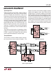
AC Cable Termination
Cable termination resistors are necessary to prevent un-
wanted reflections, but they consume power. The typical
differential output voltage of the driver is 2V when the
cable is terminated with two 120Ω resistors, causing
33mA of DC current to flow in the cable when no data is
being sent. This DC current is about 60 times greater than
the supply current of the LTC491. One way to eliminate the
unwanted current is by AC coupling the termination resis-
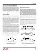
tors as shown in Figure 14.
The coupling capacitor must allow high-frequency energy
to flow to the termination, but block DC and low frequen-
cies. The dividing line between high and low frequency
depends on the length of the cable. The coupling capacitor
must pass frequencies above the point where the line
represents an electrical one-tenth wavelength. The value
of the coupling capacitor should therefore be set at 16.3pF
per foot of cable length for 120Ω cables. With the coupling
capacitors in place, power is consumed only on the signal
edges, and not when the driver output is idling at a 1 or 0
state. A 100nF capacitor is adequate for lines up to 4000
feet in length. Be aware that the power savings start to
decrease once the data rate surpasses 1/(120Ω × C).
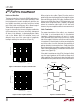
Receiver Open-Circuit Fail-Safe
Some data encoding schemes require that the output of
the receiver maintains a known state (usually a logic 1)
when the data is finished transmitting and all drivers on the
line are forced into three-state. The receiver of the LTC491
has a fail-safe feature which guarantees the output to be in
a logic 1 state when the receiver inputs are left floating
(open-circuit). However, when the cable is terminated with
120Ω, the differential inputs to the receiver are shorted
together, not left floating. Because the receiver has about
70mV of hysteresis, the receiver output will tend to main-
tain the last data bit received, but this is not guaranteed.
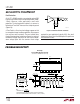
The termination resistors are used to generate a DC bias
which forces the receiver output to a known state; in the
case of Figure 15, a logic 0. The first method consumes
about 208mW and the second about 8mW. The lowest
power solution is to use an AC termination with a pull-up
resistor. Simply swap the receiver inputs for data proto-
cols ending in logic␣ 1.
LTC491 • F14
120Ω
RECEIVER
RX
C
C = LINE LENGTH (ft) x 16.3pF
Figure 14. AC Coupled Termination
Figure 15. Forcing “O” When All Drivers are Off
140Ω
RECEIVER
RX
5V
1.5kΩ
RECEIVER
RX
5V
110Ω
130Ω110Ω 130Ω
LTC491 • F15
120Ω
RECEIVER
RX
C
5V
100kΩ
1.5k