
Datasheet


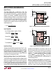

LTC6102
LTC6102-1/LTC6102HV
16
6102fe
For more information www.linear.com/LTC6102
of the amp. This form of clock feedthrough is indepen-
dent of the magnitude of the input source resistance or
the magnitude of the gain setting resistors. The LTC6102
has a residue clock feedthrough of less then 1
µV
RMS
input
referred at 10kHz.
The second form of clock feedthrough is caused by the
small amount of charge injection occurring during the
sampling and holding of the amp’s input offset voltage.
The current spikes are multiplied by the impedance seen
at the input terminals of the amp, appearing at the output
multiplied by the internal loop gain of the internal op amp.
To reduce this form of clock feedthrough, use smaller
valued gain setting resistors and minimize the source
resistance at the input.
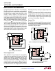
Input bias current is defined as the DC current into the
input pins of the op amp. The same current spikes that
cause the second form of clock feedthrough described
above, when averaged, dominate the DC input bias current
of the op amp below 70°C.
As temperature increases, the leakage of the ESD protec
-
tion diodes on the inputs increases the input bias currents
of both inputs in the positive direction, while the current
caused by the charge injection stays relatively constant. At
temperatures above 70°C, the leakage current dominates
and both the negative and positive pins’ input bias currents
are in the positive direction (into the pins).
Output Current Limitations Due to Power Dissipation
The L
TC6102 can deliver more than 1mA continuous cur
-
rent to the output pin. This current flows through R
IN
and
enters the current sense amp via the –INF pin. The power
dissipated in the LTC6102 due to the output current is:
P
OUT
= (V
–INF
– V
OUT
) • I
OUT
Since V
–INF
≈ V
+
, P
OUT
≈ (V
+
– V
OUT
) • I
OUT
There is also power dissipated due to the quiescent sup-
ply current:
P
Q
= I
S
• V
+
The total power dissipated is the output current dissipation
plus the quiescent dissipation:
P
TOTAL
= P
OUT
+ P
Q
applicaTions inForMaTion
At maximum supply and maximum output current, the
total power dissipation can exceed 100mW. This will
cause significant heating of the LTC6102 die. In order to
prevent damage to the LTC6102, the maximum expected
dissipation in each application should be calculated. This
number can be multiplied by the θ
JA
value listed in the
package section on page 2 to find the maximum expected
die temperature. This must not be allowed to exceed 150°C
or performance may be degraded.
As an example, if an LTC6102 in the MSOP package is to
be biased at 55V ±5V supply with 1mA output current at
80°C:
P
Q(MAX)
= I
DD(MAX)
• V
+
(MAX)
= 39mW
P
OUT(MAX)
= I
OUT
• V
+
(MAX)
= 60mW
T
RISE
= θ
JA
• P
TOTAL(MAX)
T
MAX
= T
AMBIENT
+ T
RISE
T
MAX
must be < 125°C
P
TOTAL(MAX)
≈ 99mW and the max die temp
will be 100°C
If this same circuit must run at 125°C, the max die temp
will increase to 145°C. (Note that supply current, and
therefore P
Q
, is proportional to temperature. Refer to
Typical Performance Characteristics section.) Note that
the DD package has a smaller θ
JA
than the MSOP pack-
age, which will substantially reduce the die temperature
at similar power levels.
The LTC6102HV can be used at voltages up to 105V
. This
additional voltage requires that more power be dissipated
for a given level of current. This will further limit the allowed
output current at high ambient temperatures.
It is important to note that the LTC6102 has been designed
to provide at least 1mA to the output when required, and
can deliver more depending on the conditions. Care must
be taken to limit the maximum output current by proper
choice of sense and input resistors and, if input fault
conditions are likely, an external clamp.