
Datasheet


LTC6655
14
6655fd
For more information www.linear.com/LTC6655
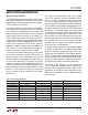
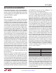
Figure 10a. Long-Term Drift MS8
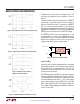
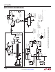
Figure 10b. Long-Term Drift LS8
applicaTions inForMaTion
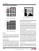
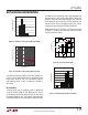
Figure 11. Hysteresis Plot –40°C to 125°C
Hysteresis
Thermal hysteresis is a measure of change of output
voltage as a result of temperature cycling. Figure 11
illustrates the typical hysteresis based on data taken from
the LTC6655-2.5. A proprietary design technique minimizes
thermal hysteresis.
Humidity Sensitivity
Plastic mould compounds absorb water. With changes in
relative humidity, plastic packaging materials change the
amount of pressure they apply to the die inside, which
can cause slight changes in the output of a voltage refer
-
ence, usually on the order of 100ppm. The LS8 package is
hermetic, so it is not affected by humidity
, and is therefore
more stable in environments where humidity may be a
DISTRIBUTION (ppm)
–90
NUMBER OF UNITS
20
25
50
15
10
–50 –10
–70 90
–30 10
70
30
110
5
0
30
6655 F11
HOURS
0
LONG-TERM DRIFT (ppm)
40
80
120
2000
6655 F10
0
–40
–80
500
1000
1500
2500
4 TYPICAL UNITS
LTC6655-2.5
MS8 PACKAGE
HOURS
0
LONG-TERM DRIFT (ppm)
40
120
200
2400
6655 F10b
–40
–120
0
80
160
–80
–160
–200
600
1200
1800
3000
LTC6655-2.5
LS8 PACKAGE
concern. However, PC board material may absorb water
and apply mechanical stress to the LTC6655LS8. Proper
board materials and layout are essential.
For best stability, the PC board layout is critical. Change
in temperature and position of the PC board, as well as
aging, can alter the mechanical stress applied to compo
-
nents soldered to the board. FR4 and similar materials also
absorb water, causing the board to swell. Even conformal
coating or potting of the board does not always eliminate
this effect, though it may delay the symptoms by reducing
the rate of absorption.
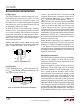
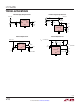
Power and ground planes should be omitted under the
voltage reference IC for best stability. Figure 12a shows a
tab cut through the PC board on three sides of an LTC6655,
which significantly reduces stress on the IC, as described
in Application Note 82. For even better performance, Figure
12b shows slots cut through the PC board on all four sides.
The slots should be as long as possible, and the corners
just large enough to accommodate routing of traces. It
has been shown that for PC boards designed in this way,
humidity sensitivity can be reduced to less than 35ppm
for a change in relative humidity of approximately 60%.
Mounting the reference near the center of the board, with
slots on four sides, can further reduce the sensitivity to
less than 10ppm.
An additional advantage of slotting the PC board is that the
LTC6655 is thermally isolated from surrounding circuitry.
This can help reduce thermocouple effects and improve
accuracy.