
Datasheet


9
LTC690/LTC691
LTC694/LTC695
U
S
A
O
PP
L
IC
AT
I
WU
U
I FOR ATIO
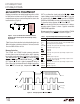
size double layer capacitors, can be used for short term
memory back-up instead of a battery. The charging resis-
tor for both capacitors and rechargeable batteries should
be connected to V
OUT
since this eliminates the discharge
path that exists when the resistor is connected to V
CC
(Figure 3).
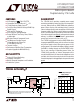
of external PNP transistor (Figure 2). If higher currents are
needed with the LTC690 and LTC694, a high current
Schottky diode can be connected from the V
CC
pin to the
V
OUT
pin to supply the extra current.
Figure 2. Using BATT ON to Drive External PNP Transistor
The LTC690 family is protected for safe area operation
with short-circuit limit. Output current is limited to ap-
proximately 200mA. If the device is overloaded for long
period of time, thermal shutdown turns the power switch
off until the device cools down. The threshhold tempera-
ture for thermal shutdown is approximately 155°C with
about 10°C of hysteresis which prevents the device from
oscillating in and out of shutdown.
The PNP switch used in competitive devices was not
chosen for the internal power switch because it injects
unwanted current into the substrate. This current is col-
lected by the V
BATT
pin in competitive devices and adds to
the charging current of the battery which can damage
lithium batteries. The LTC690 family uses a charge pumped
NMOS power switch to eliminate unwanted charging
current while achieving low dropout and low supply cur-
rent. Since no current goes to the substrate, the current
collected by V
BATT
pin is strictly junction leakage.
A 125Ω PMOS switch connects the V
BATT
input to V
OUT
in
battery back-up mode. The switch is designed for very low
dropout voltage (input-to-output differential). This feature
is advantageous for low current applications such as
battery back-up in CMOS RAM and other low power CMOS
circuitry. The supply current in battery back-up mode is
1µA maximum.
The operating voltage at the V
BATT
pin ranges from 2.0V to
4.25V. High value capacitors, such as electrolytic or farad-
Replacing the Back-Up Battery
When changing the back-up battery with system power
on, spurious resets can occur while battery is removed
due to battery standby current. Although battery standby
current is only a tiny leakage current, it can still charge up
the stray capacitance on the V
BATT
pin. The oscillation
cycle is as follows: When V
BATT
reaches within 50mV of
V
CC
, the LTC690 switches to battery back-up. V
OUT
pulls
V
BATT
low and the device goes back to normal operation.
The leakage current then charges up the V
BATT
pin again
and the cycle repeats.
If spurious resets during battery replacement pose no
problems, then no action is required. Otherwise, a resistor
from V
BATT
to GND will hold the pin low while changing the
battery. For example, the battery standby current is 1µA
maximum over temperature and the external resistor
required to hold V
BATT
below V
CC
is:
With V
CC
= 4.5V, a 4.3M resistor will work. With a 3V
battery, this resistor will draw only 0.7µA from the battery,
which is negligible in most cases.
R
V – 50mV
1A
CC
≤
µ
5V
3V
0.1µF
0.1µ
F
V
BATT
V
CC
LTC691
LTC695
V
OUT
GND
4
3
1
2
5
ANY PNP POWER TRANSISTOR
690 F02
BATT ON
5V
3V
0.1µF
0.1µ
F
V
BATT
V
CC
LTC690
LTC691
LTC694
LTC695
V
OUT
GND
690 F03
V
OUT
– V
BATT
R
I =
R
Figure 3. Charging External Battery Through V
OUT