
Datasheet

LTC6991
14
6991fb
APPLICATIONS INFORMATION
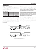
Basic Operation
The simplest and most accurate method to program the
LTC6991 is to use a single resistor, R
SET
, between the SET
and GND pins. The design procedure is a 3-step process.
First select the POL bit setting and N
DIV
value, then calculate
the value for the R
SET
resistor.
Alternatively, Linear Technology offers the easy to use
TimerBlox Designer tool to quickly design any LTC6991
based circuit. Download the free TimerBlox Designer
software at
www.linear.com/timerblox.
Step 1: Select the POL Bit Setting
The LTC6991 can operate in normal (active-high) or inverted
(active-low) modes, depending on the setting of the POL
bit. The best choice depends on the the application.
Step 2: Select the N
DIV
Frequency Divider Value
As explained earlier, the voltage on the DIV pin sets the
DIVCODE which determines both the POL bit and the N
DIV
value. For a given output clock period, N
DIV
should be
selected to be within the following range.
t
OUT
16.384ms
≤ N
DIV
≤
t
OUT
1.024ms
(1)
To minimize supply current, choose the lowest N
DIV
value
(generally recommended). Alternatively, use Table 1
as a guide to select the best N
DIV
value for the given
application.
With POL already chosen, this completes the selection of
DIVCODE. Use Table 1 to select the proper resistor divider
or V
DIV
/V
+
ratio to apply to the DIV pin.
Step 3: Calculate and Select R
SET
The final step is to calculate the correct value for R
SET
using the following equation.
R
SET
=
50k
1.024ms
•
t
OUT
N
DIV
(2)
Select the standard resistor value closest to the calculated
value.
Example: Design a 1Hz oscillator with minimum power
consumption and active-high reset input.
Step 1: Select the POL Bit Setting
For noninverted (active-high) functionality, choose
POL = 0.
Step 2: Select the N
DIV
Frequency Divider Value
Choose an N
DIV
value that meets the requirements of
Equation (1), using t
OUT
= 1000ms:
61.04 ≤ N
DIV
≤ 976.6
Potential settings for N
DIV
include 64 and 512. N
DIV
= 64
is the best choice, as it minimizes supply current by us-
ing a large R
SET
resistor. POL = 0 and N
DIV
= 64 requires
DIVCODE = 2. Using Table 1, choose R1 = 976k and
R2 = 182k values to program DIVCODE = 2.
Step 3: Select R
SET
Calculate the correct value for R
SET
using Equation (2).
R
SET
=
50k
1.024ms
•
1000ms
64
= 763k
Since 763k is not available as a standard 1% resistor,
substitute 768k if a –0.7% frequency shift is acceptable.
Otherwise, select a parallel or series pair of resistors such
as 576k + 187k to attain a more precise resistance.
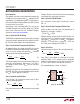
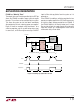
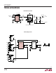
The completed design is shown in Figure 11.
DIVCODE = 2
6991 F11
LTC6991
RST
GND
SET
RST OUT
V
+
DIV
R1
976k
R2
182k
R
SET
763k
2.25V TO 5.5V
Figure 11. 1Hz Oscillator