
Datasheet


LTC6992-1/LTC6992-2/
LTC6992-3/LTC6992-4
5
69921234fc
Note 1: Stresses beyond those listed under Absolute Maximum Ratings
may cause permanent damage to the device. Exposure to any Absolute
Maximum Rating condition for extended periods may affect device
reliability and lifetime.
Note 2: The LTC6992C is guaranteed functional over the operating
temperature range of –40°C to 85°C.
Note 3: The LTC6992C is guaranteed to meet specified performance from
0°C to 70°C. The LTC6992C is designed, characterized and expected to
meet specified performance from –40°C to 85°C but it is not tested or
QA sampled at these temperatures. The LTC6992I is guaranteed to meet
specified performance from –40°C to 85°C. The LTC6992H is guaranteed
to meet specified performance from –40°C to 125°C. The LTC6992MP is
guaranteed to meet specified performance from –55°C to 125°C.
Note 4: Frequency accuracy is defined as the deviation from the f
OUT
equation, assuming R
SET
is used to program the frequency.
Note 5: See Operation section, Table 1 and Figure 2 for a full explanation
of how the DIV pin voltage selects the value of DIVCODE.
Note 6: Duty cycle settling time is the amount of time required for the
output to settle within ±1% of the final duty cycle after a ±10% change in
the setting (±80mV step in V
MOD
).
Note 7: To conform to the Logic IC Standard, current out of a pin is
arbitrarily given a negative value.
Note 8: Output rise and fall times are measured between the 10% and the
90% power supply levels with 5pF output load. These specifications are
based on characterization.
Note 9: Jitter is the ratio of the peak-to-peak deviation of the period to the
mean of the period. This specification is based on characterization and is
not 100% tested.
Note 10: Long-term drift of silicon oscillators is primarily due to the
movement of ions and impurities within the silicon and is tested at 30°C
under otherwise nominal operating conditions. Long-term drift is specified
as ppm/√kHr due to the typically nonlinear nature of the drift. To calculate
drift for a set time period, translate that time into thousands of hours, take
the square root and multiply by the typical drift number. For instance, a
year is 8.77kHr and would yield a drift of 266ppm at 90ppm/√kHr. Drift
without power applied to the device may be approximated as 1/10th of the
drift with power, or 9ppm/√kHr for a 90ppm/√kHr device.
elecTrical characTerisTics
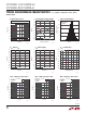
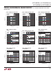
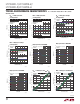
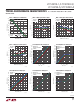
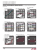
Typical perForMance characTerisTics
Frequency Error vs Temperature Frequency Error vs Temperature Frequency Error vs Temperature
V
+
= 3.3V, R
SET
= 200k, and T
A
= 25°C, unless
otherwise noted.
TEMPERATURE (°C)
–50
–3
0
1
2
3
0 25 50
100 125
–1
–2
–25
75
6992 G01
ERROR (%)
R
SET
= 50k
3 PARTS
GUARANTEED MAX OVER TEMPERATURE
GUARANTEED MIN OVER TEMPERATURE
TEMPERATURE (°C)
–50
–3
0
1
2
3
0 25 50
100 125
–1
–2
–25
75
6992 G02
ERROR (%)
R
SET
= 200k
3 PARTS
GUARANTEED MAX OVER TEMPERATURE
GUARANTEED MIN OVER TEMPERATURE
TEMPERATURE (°C)
–50
–3
0
1
2
3
0 25 50
100 125
–1
–2
–25
75
6992 G03
ERROR (%)
R
SET
= 800k
3 PARTS
GUARANTEED MAX OVER TEMPERATURE
GUARANTEED MIN OVER TEMPERATURE