
Datasheet

LTM2881
15
2881fg
For more information www.linear.com/LTM2881
APPLICATIONS INFORMATION
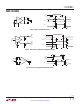
Switchable Termination
Proper cable termination is very important for signal fi-
delity. If the cable is not terminated with its characteristic
impedance, reflections will distort the signal waveforms.
The integrated switchable termination resistor provides
logic control of the line termination for optimal per
for
-
mance when configuring transceiver networks.
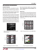
When the TE pin is high, the termination resistor is enabled
and the differential resistance from A to B is 120Ω. Figure
11 shows the I/V characteristics between pins A and B
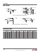
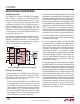
with the termination resistor enabled and disabled. The
resistance is maintained over the entire RS485 common
mode range of –7V to 12V as shown in Figure 12. The
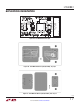
integrated termination resistor has a high frequency re
-
sponse which does not limit performance at the maximum
specified data rate. Figure 13 shows the magnitude and
Figure 13. Termination Magnitude and Phase vs Frequency
Figure 12. Termination Resistance vs Common Mode Voltage
Figure 11. Curve Trace Between A and B with Termination
Enabled and Disabled
2881 F11
COMMON MODE VOLTAGE (V)
RESISTANCE (Ω)
130
128
126
124
122
120
118
116
114
112
110
2881 G11
15105–5 0–10
FREQUENCY (MHz)
MAGNITUDE (Ω)
PHASE (DEGREES)
150
140
130
120
110
100
10
0
–10
–20
–30
–40
2881 F13
1010.1
PHASE
MAGNITUDE
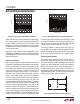
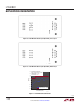
Figure 14. Supply Current vs Data Rate
DATA RATE (Mbps)
2881 F14
1010.1
SUPPLY CURRENT (mA)
250
230
210
190
170
150
130
110
90
70
50
LTM2881-3
R=54 CL=1000p
R=54 CL=100p
R=54 CL=0
LTM2881-5
R=54 CL=1000p
R=54 CL=100p
R=54 CL=0
phase of the termination impedance versus frequency.
The termination resistor cannot be enabled by TE if the
device is unpowered, ON is low or the LTM2881 is in
thermal shutdown.
Supply Current
The static supply current is dominated by power delivered to
the termination resistance. Power supply current increases
with data rate due to capacitive loading. Figure 14 shows
supply current versus data rate for three different loads
for the circuit configuration of Figure 4. Supply current
increases with additional external applications drawing
current from V
CC2
.