
Datasheet


LTM4644/LTM4644-1
13
Rev. F
For more information www.analog.com
APPLICATIONS INFORMATION
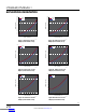
Figure 3. Normalized RMS Ripple Current for Single Phase or Polyphase Applications
DUTY CYCLE (V
OUT
/V
IN
)
0.1 0.15 0.2 0.25 0.3 0.35 0.4 0.45 0.5 0.55 0.6 0.65 0.7 0.75 0.8
0.85 0.9
0.60
0.55
0.50
0.45
0.40
0.35
0.30
0.25
0.20
0.15
0.10
0.05
0
4644 F03
RMS INPUT RIPPLE CURRENT
DC LOAD CURRENT
1-PHASE
2-PHASE
4-PHASE
Output voltage tracking can also be programmed externally
using the TRACK/SS pin of each regulator channel. The
output can be tracked up and down with another regula
-
tor. Figure 4 and Figure 5 show an example waveform
and schematic of a ratiometric tracking where the slave
regulator’s (V
OUT2
, V
OUT3
and V
OUT4
) output slew rate is
proportional to the master’s (V
OUT1
).
Since the slave regulator’s TRACK/SS is connected to
the master’s output through a R
TR(TOP)
/R
TR(BOT)
resistor
divider and its voltage used to regulate the slave output
voltage when TRACK/SS voltage is below 0.6V, the slave
output voltage and the master output voltage should satisfy
the following equation during the start-up.
V
OUT(SL)
•
R
FB(SL)
R
FB(SL)
+ 60.4k
= V
OUT(MA)
•
R
TR(BOT)
R
TR(TOP)
+R
TR(BOT)
Where the 60.4k is the integrated top feedback resistor
and the R
FB(SL)
is the external bottom feedback resistor
of the LTM4644. The R
TR(TOP)
/R
TR(BOT)
is the resistor
divider on the TRACK/SS pin of the slave regulator, as
shown in Figure 5.
Following the upper equation, the master’s output slew
rate (MR) and the slave’s output slew rate (SR) in volts/
time is determined by:
MR
SR
=
R
FB(SL)
R
FB(SL)
+ 60.4k
R
TR(BOT)
R
TR(TOP)
+R
TR(BOT)
Downloaded from Arrow.com.Downloaded from Arrow.com.Downloaded from Arrow.com.Downloaded from Arrow.com.Downloaded from Arrow.com.Downloaded from Arrow.com.Downloaded from Arrow.com.Downloaded from Arrow.com.Downloaded from Arrow.com.Downloaded from Arrow.com.Downloaded from Arrow.com.Downloaded from Arrow.com.Downloaded from Arrow.com.